

fig4
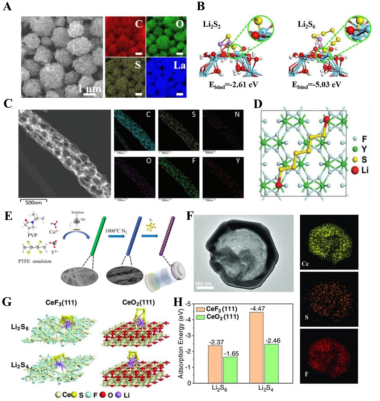
Figure 4. (A) Morphology of composite sulfur electrode and corresponding EDS mapping; (B) Optimized polysulfide adsorption structures and calculated binding energy. The figures are quoted with permission from Tian et al.[91]; (C) HRTEM images of YF3 nanofiber and corresponding EDS mapping; (D) Optimized YF3 structure. The figures are quoted with permission from Hao et al.[92]; (E) Preparation process of CoF3co-doping into YF3 carbon nanofiber and corresponding morphologies. This figure is quoted with permission from Wang et al.[93]; (F) HRTEM image of Hollow- CeF3 and corresponding EDS mapping; (G) Optimized polysulfide adsorption structures on the surface of CeF3 and CeO2; (H) Adsorption energy comparison between CeF3 and CeO2. The figures are quoted with permission from Liu et al.[94]. PVP: Polyvinyl pyrrolidone; PTFE: polytetrafluoroethylene; EDS: energy-dispersive X-ray spectroscopy; HRTEM: high-resolution transmission electron microscopy.

