



Review of the forming progress and challenges of carbon-resin composite bipolar plates and their flow field
 0
0 Abstract
With the rapid development of large-scale energy storage technologies, redox flow batteries are considered a promising pathway for large-scale energy storage due to their advantages of decoupled energy and power, long cycle life, and high safety. As key components that affect battery efficiency and lifetime, bipolar plates not only serve as current collectors and structural supports but also enable electrolyte distribution via surface flow fields. Carbon-resin composite bipolar plates have become a research hotspot due to their outstanding compositional tunability and structural design flexibility. Adding a flow field to these bipolar plates can efficiently enhance battery efficiency without the need for additional material development. But as flow field structures become increasingly complex, carbon-resin composite bipolar plates face new manufacturing challenges during flow field forming. Unlike previous reviews that focus solely on the forming of bipolar plates while neglecting the additional challenges posed by flow fields, this review summarizes recent progress in material design optimization and structural innovation for carbon-resin composite bipolar plates. It analyzes the design characteristics of various flow field structures and their corresponding forming challenges. These insights provide a reference for further improvement and large-scale manufacturing of carbon-resin composite bipolar plates with integrated flow fields.
Keywords
INTRODUCTION
Since the first industrial revolution, fossil fuels have long dominated the global power supply. Their excessive use not only raises concerns about energy security but also leads to numerous severe environmental problems, including air pollution, greenhouse gas emissions, and acid rain[1,2]. These challenges drive the urgent search for clean alternative energy sources. Renewable energy sources with extremely low greenhouse gas emissions, such as solar, wind, and tidal energy, have become important options for sustainable electricity generation[3]. However, the inherent intermittency and unpredictability of these resources may cause fluctuations in the power grid and reduce the reliability of the electricity supply. Therefore, large-scale energy storage systems are urgently needed to smooth these fluctuations and stabilize the grid[4,5].
Among various energy storage technologies, electrochemical energy storage systems have attracted significant attention due to their high efficiency, flexibility, and scalability. However, for large-scale energy storage technologies, high system power and capacity mean that safety incidents can cause severe damage and losses. Therefore, safety and reliability are the primary requirements for energy storage technologies[6]. Carbon-based materials have broad application potential in electrochemistry due to their high electrical conductivity, high specific surface area, and chemical stability. Its unique properties stem from the precise atomic-scale structure, including the sp2-hybridized carbon-atom network and the delocalized π-electron system. In electrochemical applications, the design of carbon-based materials has emerged as a cutting-edge research frontier. Cutting-edge technologies focus on multiscale structural regulation and synergistic functional optimization to enhance catalyst performance and stability. These applications span multiple fields, including fuel cells, metal-air batteries, water electrolysis, carbon dioxide (CO2) reduction, and sensors[7,8]. Since its initial development by NASA in the 1970s[9], redox flow battery (RFB) technology has undergone extensive exploration of various redox couples and continuous optimization of reaction structures[10-13], gradually evolving from microgrid demonstrations toward large-scale grid applications[14]. Owing to their intrinsic safety characteristics, RFBs have become one of the most promising and irreplaceable technologies for large-scale energy storage [Figure 1].
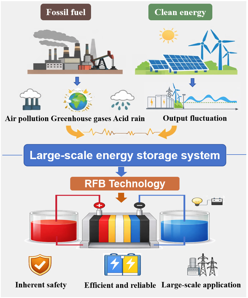
Figure 1. Environmental impacts of traditional energy industries and advantages of renewable energy. RFB: Redox flow battery.
RFBs are a class of electrochemical energy storage systems that store and release energy through reversible redox reactions in liquid electrolytes[15]. Taking the typical vanadium redox flow battery (VRFB) as an example, its basic configuration consists of a stack, electrolyte storage tanks, and circulation pumps[16]. The active species are dissolved in the electrolyte, stored in separate tanks, and then pumped into the stack, where redox reactions occur within the reaction cells, thereby completing the charge and discharge processes. Unlike conventional lithium-ion batteries, the power of RFB systems is determined by stack size, whereas energy capacity is governed by electrolyte volume. This configuration enables independent control of power and energy[17]. Although VRFBs exhibit significant advantages in system stability and cycle life, challenges remain regarding energy efficiency, volumetric power density, and cost control[18].
As the core component of RFB systems, the overall performance of the stack largely depends on the integrated performance of several key materials[19]. The bipolar plate is a core component of a flow battery, and its performance directly affects the battery stack’s output power, service life, and cost. The bipolar plate plays multiple roles within the stack and accounts for 24%-38% of the total cost. In addition, the proportion of the bipolar plate and current collector that is in contact decreases with increasing numbers of battery cells, from 1%-22%. The bipolar plates perform the following critical functions: (1) Separation and sealing: Physically isolate the electrolyte between the positive and negative sides, preventing direct mixing of electrolytes that could pose hazards; (2) Current conduction: Act as a conductive bridge between the positive and negative electrodes, collecting and conducting electrons while connecting multiple individual cells in series; (3) Reduced pressure drop and optimized electrolyte distribution: The meticulously designed flow fields on the plate surface enable electrolyte transport without passing through the electrodes, significantly enhancing delivery efficiency while minimizing pressure drop and ensuring efficient reaction progression; (4) Mechanical properties: Serve as a support structure for the battery stack[20]. Therefore, the material selection and structural design of bipolar plates directly determine the stack’s internal resistance and mechanical reliability. They also critically influence the battery system’s long-term stability, ultimately determining its energy efficiency and cycle life. Meanwhile, the introduction of the flow field can enhance overall performance without increasing the cost of additional material research and development[21].
Due to the extremely harsh operating environment of RFB systems, although bipolar plates play similar roles in many electrochemical energy storage devices, the material selection of BPs in RFBs is severely restricted[22]. Therefore, despite their excellent electrical conductivity and mechanical strength, metallic bipolar plates without protective coatings are difficult to use in flow batteries with highly corrosive electrolytes[23]. Even corrosion-resistant metals such as stainless steel and titanium alloys may suffer from pitting corrosion, crevice corrosion, or passive film failure during long-term operation. Once corrosion occurs, insulating corrosion products formed on the bipolar plate surface significantly increase contact resistance[24]. In addition, dissolved metal ions may enter the electrolyte, disrupting its chemical stability[25]. Currently, only a few studies attempt to unlock the potential of metallic bipolar plates through surface protection strategies[26]. For example, Han et al. fabricated an electrocatalytically active bipolar plate by anodizing a titanium substrate to form a TiO2 nanotube array. Subsequently, an IrOx coating was deposited on the surface[27]. Compared with graphite bipolar plates, the battery’s voltage and energy efficiencies increase by 3%-4%. However, due to the relatively high density of metals, metallic bipolar plates are unfavorable for large-scale applications. Moreover, the use of noble metals or corrosion-resistant coatings leads to high costs and complex fabrication processes. On the other hand, non-porous graphite plates suffer from several drawbacks, including high brittleness, susceptibility to cracking, difficulties in machining, high cost, limited sealing performance, and relatively large weight. These limitations make it difficult to meet the requirements of flow batteries for large size, low cost, and high reliability[28-30].
Overall, carbon-resin composite bipolar plates (CBPs) achieve good electrical conductivity while maintaining corrosion resistance by introducing a polymer resin matrix into conductive carbon materials. In addition, their relatively low density and formability via extrusion or compression molding make them suitable for mass production and the integrated manufacturing of complex flow fields. These advantages provide significant benefits for cost control and large-scale applications. CBPs not only effectively alleviate the brittleness and machining difficulties associated with graphite plates but also achieve a favorable balance among electrical conductivity, mechanical strength, corrosion resistance, and formability[31]. However, this material-level balance does not directly translate into manufacturable performance when complex flow fields are introduced. It is fundamentally constrained by the coupling between material system selection (e.g., thermoplastic vs. thermosetting matrices, filler characteristics) and the geometric complexity and precision requirements of flow field structures, which together determine the flow field’s formability.
A well-designed flow field can optimize the velocity distribution and the electrolyte concentration gradient on the electrode surface, thereby reducing concentration polarization and pressure-drop losses while improving the utilization of active species[32,33]. Meanwhile, as flow field structures become increasingly complex and refined, the issue of forming precision for BPs becomes more prominent. Carbon-resin composites are typically fabricated through compression molding or extrusion processes[34]. Their flow behavior, filler distribution, and shrinkage characteristics directly affect the dimensional precision (the degree of conformity between the actual and designed sizes) and surface quality (surface flatness or roughness, etc.) of microscale flow fields[35]. Various forming defects may not only alter the actual fluid resistance and flow distribution but also influence electrode compaction and interfacial contact resistance[36-38]. In addition, resin enrichment at the surfaces of the flow fields or uneven orientation of conductive carbon fillers may reduce local electrical conductivity and structural strength, thereby increasing the risk of deformation or leakage during long-term operation[39,40]. Therefore, in CBP systems, material design and structural design can no longer be considered independent issues but rather a coupled process requiring coordinated optimization. Forming processes are required to ensure precise replication of flow field structures. How to achieve high-precision flow field replication and long-term structural stability while maintaining the formability of large-scale manufacturing has become a key scientific and technological challenge for the further engineering application of CBPs.
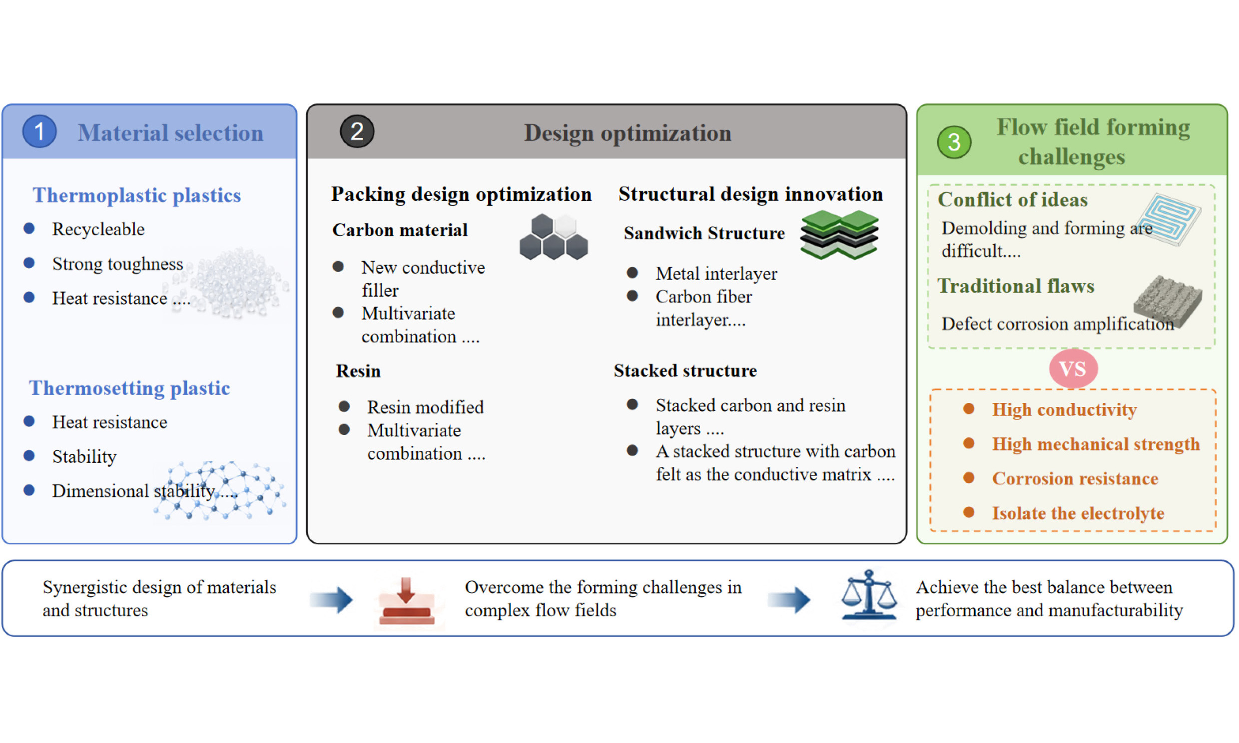
As shown in Figure 2, this paper systematically reviews the development trajectory and recent progress in research on CBPs in RFBs. From multiple perspectives, including filler design, structural optimization, and flow field formation, the latest advances and representative achievements of CBPs for RFBs are summarized.
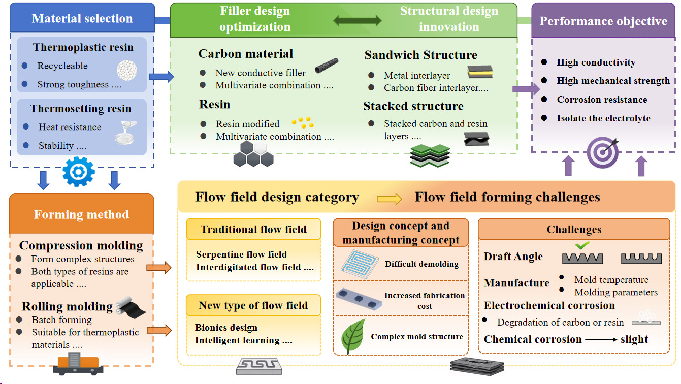
Figure 2. Innovative design strategies of carbon-resin composite bipolar plates and the challenges in flow field formation.
Particular attention is given to the potential influence of the current optimization strategies for thermoplastic and thermosetting CBPs on flow field forming. In addition, based on recent developments in flow field design, this paper systematically discusses the corresponding forming challenges. These analyses provide useful references for the development of RFBs with high performance, low cost, and long service life. They also establish a theoretical and engineering foundation for subsequent studies on material selection, structural and flow field optimization, and precision forming processes of CBPs.
CLASSIFICATIONS AND IMPROVEMENTS OF CBPS
CBPs are typically composed of conductive carbon materials (such as graphite, carbon black, and carbon fibers) and polymer matrices, including thermosetting and thermoplastic resins[41,42]. The carbon components establish conductive pathways, whereas the polymer matrix offers structural robustness and processability. Importantly, the selection of a filler system not only determines the intrinsic properties of CBPs but also directly governs their formability (the material’s ability to be shaped into a desired geometry) and manufacturability (the practical feasibility of producing the component at scale), especially for flow field structures. Through rational design, a balance between electrical conductivity and mechanical strength can be achieved.
Thermoplastic CBPs use thermoplastic polymers such as polypropylene (PP), polyethylene (PE), and polytetrafluoroethylene (PTFE) as the matrix[43]. These materials soften upon heating and solidify upon cooling, exhibiting good processability and recyclability[44]. Simultaneously, its ability to be processed by melting allows for the effective reproduction of flow field structures via continuous forming methods. Processes such as hot pressing, extrusion molding, and rolling allow rapid forming and large-area manufacturing, thereby significantly reducing production costs[45,46]. However, a high content of conductive fillers markedly decreases melt flowability and weakens interfacial bonding strength. Meanwhile, thermoplastic resins generally possess relatively low thermal resistance and dimensional stability, making them susceptible to creep deformation under long-term compression or elevated operating temperatures[47].
Thermosetting CBPs typically employ resins such as phenolic resin (PF) and epoxy resin (EP) as the matrix. During curing, these resins form highly crosslinked three-dimensional network structures. Such structures provide excellent dimensional stability and enable the accurate retention of molded flow field geometries. Their main advantages are the dense structure formed after curing and superior thermal resistance, making them suitable for relatively harsh operating environments[48]. From a manufacturing perspective, the irreversible curing process restricts post-forming adjustment and recycling, and introduces difficulties in achieving both high precision and in flow field fabrication. In addition, the curing process of thermosetting resins is irreversible, leading to long processing cycles and difficulty in recycling[49].
In terms of forming processes, thermosetting resins are typically mixed and impregnated first, then compressed under heat and pressure to cure and shape[50]. This approach is suitable for systems with high filler content and allows complex flow field structures to be formed in a single step. However, the irreversible curing process introduces challenges such as shrinkage stress and dimensional control. By contrast, thermoplastic resins rely on their melt-processable characteristics. Conductive fillers are usually dispersed through melt blending or extrusion mixing, followed by processes such as rolling, extrusion, or hot-press molding to construct plate structures and flow field geometries[20,34,51]. The advantages of thermoplastic systems include reprocessability, high forming efficiency, and suitability for continuous production. Nevertheless, high filler loading significantly reduces melt flowability, making it more challenging to achieve replication accuracy and forming stability for complex micro-scale flow field structures. Recent research on CBPs has further extended into two major directions: filler design optimization and structural design innovation, both aimed at improving the overall performance of BPs. Optimization of filler design enhances conductive networks and interfacial bonding. This can be achieved by introducing novel carbon materials with different dimensional structures or by modifying existing resin systems. Meanwhile, innovations in structural design have become another important pathway for performance enhancement. Traditional homogeneous structures are increasingly unable to satisfy the requirements for high conductivity and corrosion resistance simultaneously. Consequently, researchers begin to explore multilayer, stacked, and multiscale structural design strategies. At the same time, different resin systems, combined with corresponding forming processes, exhibit distinct advantages across various aspects, offering diverse pathways for structural regulation and performance optimization of BPs.
THERMOPLASTIC CBPS
Filler design optimizations of thermoplastic CBPs
As a key component in RFBs, the BP primarily functions as a barrier separating the positive and negative electrolytes[52]. Thermoplastic resins exhibit fluidity upon softening at elevated temperatures, allowing them to penetrate forming defects in the interior or on the surface of the BP, thereby reducing the risk of acidic electrolytes infiltrating the plate and causing internal swelling. At the same time, such flowability is essential for replicating flow field geometries but is highly sensitive to filler loading and dispersion.
Kim et al. spray thermoplastic PTFE in emulsion form onto expanded graphite powder[53], as shown in Figure 3. The mixture is first compression-molded into a preform and then processed through multi-step rolling for final shaping. BPs containing 6% or 10% PTFE exhibit almost no observable swelling after cycling compared with flexible graphite plates. This result indicates that the thermoplastic resin in conventional thermoplastic CBPs effectively suppresses swelling. In addition, Kang et al. use a similar fabrication route[54], further confirming that PVDF, after hot pressing, effectively repairs the surface and cross-sectional microcracks in expanded graphite. It also suggests that appropriate resin distribution can improve structural integrity during forming, thereby helping maintain flow field stability.
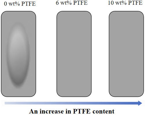
Figure 3. Surfaces of bipolar plates with different PTFE contents after single-cell cycling. PTFE: polytetrafluoroethylene.
Meanwhile, the electrical conductivity of CBPs does not increase linearly with increasing carbon content. Instead, when the content of conductive carbon materials reaches the percolation threshold, the electrical properties of the composite undergo a transition from an insulating to a conductive state. The percolation threshold of conductive fillers is strongly influenced by the particle size, morphology, and distribution of the fillers within the polymer matrix[55]. These parameters simultaneously affect rheological behavior, which directly determines the formability of flow field structures during processing. Many studies introduce a large amount of conductive filler to establish sufficient conductive pathways[56]. However, excessive filler loading inevitably increases the risk of fracture in the BP. To address this issue, Liao et al. developed a ternary conductive system composed of graphene, graphite powder, and chopped carbon fibers, which forms an efficient conductive network at relatively low carbon content[57]. At a carbon content of only 25 wt%, both the electrical and mechanical properties meet the 2020 Department of Energy (DOE)[58] standards. Importantly, reducing filler content also helps retain sufficient flowability, which is beneficial for accurate flow field replication. Jiang et al. further designed cactus-like carbon nanofibers[59]. In this structure, fibers radiate outward from a catalytic core, forming a three-dimensional clustered architecture. After graphitization at 2,800 °C, graphitized cactus-like carbon nanofibers (G-C-CNF) are obtained, which exhibit significantly improved graphitization and structural integrity. This architecture disrupts resin-rich surface layers, thereby improving both electrical contact and the effective exposure of flow field structures, as shown in Figure 4.
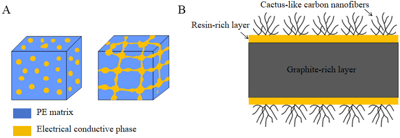
Figure 4. Schematic diagram of the conductive network and cactus-shaped carbon nanofibers (4): (A) Microstructural schematic of the highly efficient conductive network in the bipolar plate; and (B) Schematic diagram of the bipolar plate modified with C-CNF. PE: Polyethylene; C-CNF: cactus-like carbon nanofiber.
In addition, Qin et al. optimize both electrical and mechanical properties at low carbon content by incorporating multi-dimensional carbon materials[60]. Zero-dimensional filler Ketjen black (KB), one-dimensional filler carbon nanotubes (CNTs), and two-dimensional filler flake graphite (FG) work synergistically to construct a three-dimensional continuous conductive network. Such a multi-dimensional filler design not only enhances conductivity but also improves dispersion uniformity, which is crucial for stable forming of intricate flow field geometries. Moreover, Zhang et al. introduce a new copolymer made from ethylene and propylene monomers[61], known as polypropylene elastomer, which improves the processability of the composite material while maintaining excellent toughness. Table 1 is a comprehensive summary of the above-mentioned literature.
Summary of main performance and conclusions of thermoplastic carbon-resin composite bipolar plate packing design
| References | Main performance | Main conclusion |
| Kim et al.[52] | Specific through-plane resistivity (mΩ·cm): 102.98 Single cell cyclic performance@100 mA/cm2: 80.8% | Thermoplastic resins play a key role in inhibiting the expansion of graphite |
| Liao et al.[57] | ASR: 3.3 mΩ·cm2; Flexural strength: 48.1 MPa; EE: 85.7% @100 mA cm⁻2 | Achieves high conductivity and strength at ultra-low carbon content via graphene bridging |
| Jiang et al.[59] | Conductivity: 198.7 S/cm; ASR: 25.4 mΩ·cm2; EE: 86.28% @100 mA cm-2 | Surface CNF eliminates the resin-rich layer and enhances conductivity and durability |
| Qin et al.[60] | Conductivity: 103.43 S/cm; Flexural strength: 26.17 MPa; EE fluctuation: ±1.5% | Multidimensional carbon network enables balanced performance at moderate filler content |
Structural design innovations of thermoplastic CBPs
The design of fillers is typically aimed at improving the performance of the BP by adjusting the ratio of carbon materials to resin. However, electrical conductivity and mechanical strength often exhibit a trade-off relationship[62]. Therefore, simply adjusting the filler ratio cannot achieve a balance between electrical and mechanical properties. Such compositional tuning not only affects intrinsic properties but also directly influences the rheological behavior and forming capability of the composite during flow field fabrication. In addition, during the forming process, differences in flowability between the resin and fillers often lead to resin enrichment at the surface or interface. This phenomenon may interrupt conductive pathways and increase interfacial contact resistance. Filler design alone is therefore fundamentally insufficient to suppress such resin enrichment from a structural perspective.
To address these challenges in thermoplastic CBPs for VRFB, researchers have proposed a variety of structural design innovations. Onyu et al. develop a layered composite structure to achieve a synergistic performance enhancement[63]. The structure adopts a stacked configuration consisting of a conductive composite layer [thermoplastic vulcanizates (TPV) combined with synthetic graphite], a woven carbon fiber fabric, and a pyrolytic graphite sheet. Such layer-wise functional separation enables local optimization of the forming process, thereby improving both structural integrity and the accuracy of flow field replication. As shown in Figure 5A, scanning electron microscopy (SEM) images reveal no obvious interfacial gaps between the layers, indicating strong interfacial bonding. Moreover, the layered structure BP has good thermal stability at high temperatures [Figure 5B]. Liu et al. replace powder-type conductive fillers with a carbon felt framework to construct a continuous conductive network[39]. Thermoplastic polyvinyl fluoride (PVDF) forms a dense layer between carbon felt through solution impregnation followed by secondary hot pressing. In this design, the pre-constructed three-dimensional conductive framework reduces the dependence on high filler loading, thereby improving processability and enabling more stable formation of flow field structures. In addition, Pavel et al. use graphite foil as a conductive substrate and impregnate fluorinated polymers into the existing pores to construct a three-dimensional conductive pathway structure[64]. After fluoropolymer impregnation, the graphite on the surface layer exhibits a certain tendency toward oriented distribution.
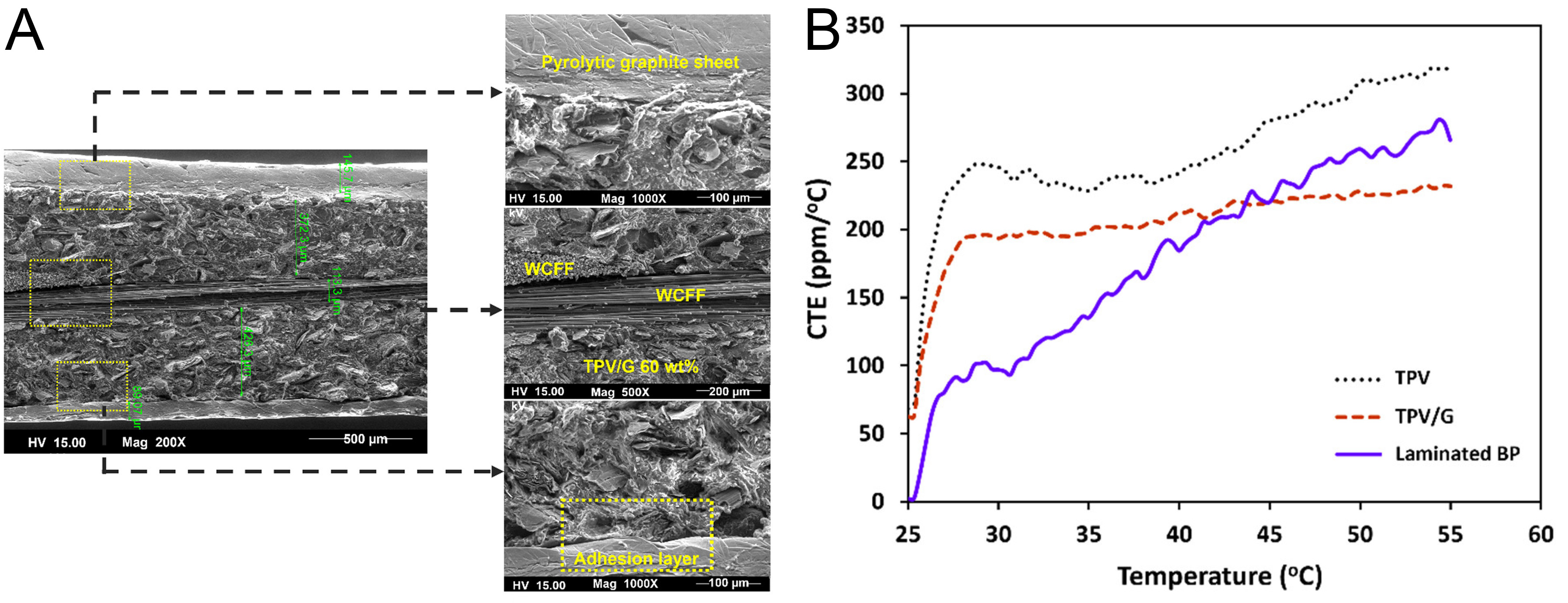
Figure 5. (A) SEM morphology of the laminated CBP; (B) The variation of the thermal expansion coefficients of TPV, TPV/G, and laminated BP with temperature. Reprinted from Ref.[63], under CC BY 4.0 license. WCFF: Woven-carbon-fiber fabric; TPV: thermoplastic vulcanizates; CTE: coefficient of thermal expansion; SEM: scanning electron microscopy; CBP: composite bipolar plate.
THERMOSETTING CBPS
Filler design optimizations of thermosetting CBPs
With increasing demands for the stability of CBPs, researchers have begun to refocus on CBPs based on thermosetting resin matrices. This shift is not only driven by performance considerations but also by the need for improved dimensional stability in flow field structures during long-term operation. Unlike thermoplastic resins, thermosetting systems form dense crosslinked networks during the curing process, which stabilize the distribution of conductive fillers even at relatively low resin content. Meanwhile, their relatively low thermal expansion coefficient and excellent structural rigidity enable superior dimensional stability and fatigue resistance during long-term operation. Such characteristics are particularly advantageous for preserving the geometric accuracy of pre-formed flow field structures under compression and thermal fluctuations. For example, Li et al. prepare phenolic-resin-based BPs by vacuum impregnation of expanded graphite (EG)[65]. The uniform penetration of resin between graphite layers significantly enhances interlayer bonding strength and blocks pore fields, enabling the plate to maintain a continuous conductive network while exhibiting excellent flexural strength and gas tightness. In addition, Choe et al. propose a new strategy by incorporating polyaniline (PANI) conductive particles into epoxy resin[66], as shown in Figure 6. PANI particles are sprayed onto the surface of the carbon fiber/epoxy composite system, forming localized conductive pathways within the resin matrix. The introduction of an appropriate amount of PANI significantly reduces contact resistance while maintaining good corrosion resistance and electrochemical stability. Such localized conductive design reduces the dependence on high overall filler loading, which is beneficial for maintaining processability during forming.
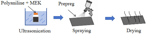
Figure 6. PANI spray preimpregnated material preparation process. MEK: Methyl ethyl ketone; PANI: polyaniline.
Structural design innovations of thermosetting CBPs
Component regulation alone cannot fully resolve issues such as the intrinsically low conductivity of the resin phase, interfacial stress concentration, and high surface resistance. More importantly, it cannot fundamentally address limitations in flow behavior and forming adaptability during flow field fabrication. Therefore, researchers further shift their focus to structural design, aiming to achieve synergistic performance enhancement by optimizing both macroscopic structures and interfacial architectures.
In research about thermosetting composite BPs, the structural design consistently emphasizes interfacial bonding, electrical conductivity, and long-term stability. Kim et al. have conducted a series of studies in this field[67]. To address crack issues in expanded graphite (EG) coatings, the team proposed a surface crack-closure method. After molding, compressive stress is applied to close microcracks in the graphite coating, thereby preventing penetration of acidic electrolyte. Such post-treatment improves structural integrity but also highlights the difficulty of controlling defects during the initial formation of flow field surfaces. In addition, Soohyun et al. first proposed integrating an E-glass/epoxy resin flow frame with a carbon fiber/epoxy resin matrix composite into a unified structure to eliminate the interface leakage inherent in traditional stacked components[68]. However, the difference in thermal expansion coefficients between the two composite materials leads to severe residual curing stresses. Structural warpage and local buckling are effectively reduced by designing an intelligent curing cycle that carefully controls the curing temperature and cooling stages. Lee et al. proposed the soft-layer method[69], in which a flexible release film is inserted between the prepreg and the mold during compression molding. Under pressure, the surface resin is squeezed out, exposing the conductive carbon fibers. This design significantly reduces area-specific resistance (ASR) without requiring additional graphite coating, while maintaining high mechanical strength and good gas tightness. It also establishes a processing foundation for subsequent multilayer composite structures. Based on the Soft Layer Method, the matrix is further expanded from conventional epoxy resin to a fluorinated elastomer system, while nano-carbon fillers are introduced to form a multiscale conductive network[70]. The excellent acid-alkali resistance and flexibility of fluorinated elastomers enable the composite plate to maintain low contact resistance and excellent mechanical stability even in highly corrosive environments; their enhanced flexibility also improves deformation compatibility during forming, which is beneficial for reducing defects in complex flow field geometries. To further reduce manufacturing costs and expand application potential, the Soft Layer Method is also applied to a non-woven carbon felt/epoxy system[71], enabling the fabrication of large-area BPs under low-pressure molding conditions. The 3D interconnected pore structure of carbon felt can form a stable vertical conductive path even under low pressure conditions, thereby reducing the sheet resistance to 22 mΩ·cm2. Such low-pressure forming conditions are advantageous for scaling up manufacturing. However, they may also limit the replication accuracy of fine flow field structures due to insufficient compaction. In addition, Choe et al. evaluate the electrochemical corrosion durability of different graphite coatings through electrochemical aging tests[72]. The results indicate that pyrolytic graphite, due to its highly oriented structure and stronger van der Waals bonding, exhibits significantly higher durability than conventional expanded flake graphite. Table 2 summarizes the main innovative points and conclusions of the above-mentioned achievements.
Main innovation points and conclusion summary
| Reference | Key innovation | Main conclusions |
| Surface crack closure method | Crack closure for defect repair | Effectively improves gas-tightness and reduces interfacial contact resistance by repairing surface defects |
| Smart curing cycle | Optimized curing to reduce residual stress | Significantly alleviates thermal residual stress and enhances structural stability |
| Carbon fiber exposure method | Fiber exposure to enhance conductivity | Promotes conductive pathway continuity and lowers contact resistance |
| Nano-carbon/fluoroelastomer composite BP | Fluoroelastomer-based conductive composite | Achieves a balance of high mechanical strength, good conductivity, and excellent chemical stability |
| Nonwoven carbon felt + soft-layer method | Felt-based conductive network with soft-layer | Enables low-pressure fabrication while meeting conductivity requirements and maintaining acceptable mechanical properties |
| Graphite-coated durability study | Graphite coating with ASR-modulus model | Establishes a structure-property relationship and improves durability and electrochemical stability |
To further overcome the structural limitations of conventional stacks, many researchers propose innovative structural design strategies. These strategies aim not only to enhance conductivity and integration, but also to retain the formability required for reliable flow field fabrication. Choe et al. develop a CBP with an integrated current collector structure[73], as shown in Figure 7. Through a co-curing process, a carbon fiber/epoxy prepreg and a metal current collector are simultaneously cured during a single hot-pressing step, forming a dense and pore-free continuous conductive network. This structure effectively eliminates the resistance increase associated with conventional bolted or conductive adhesive connections between the plate and the current collector, while minimizing interfacial contact resistance. At the same time, the integrated structure reduces interfacial discontinuities.
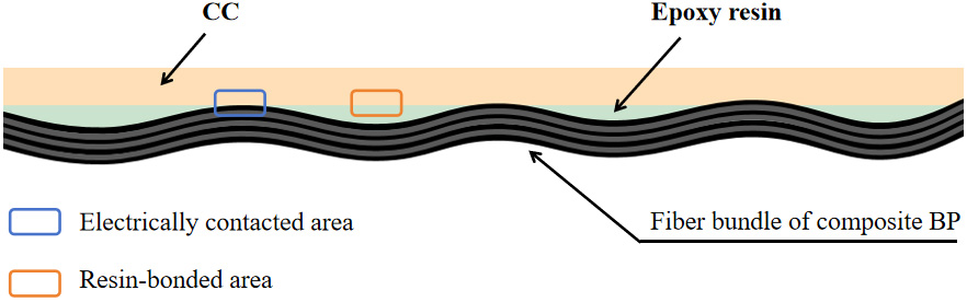
Figure 7. Schematic diagram of the cross-section of the composite structure. BP: Bipolar plate; CC: Current Collector.
Subsequently, Choe et al. further construct a CBP with a “fiber spreading effect” using spread-tow fabric[74]. Traditional one-way fabrics or thick woven fabrics frequently exhibit discontinuous in-plane conductive paths due to fiber undulation and resin retention. Spread-tow prepregs with fiber bundle sizes of 10k and 20k are prepared by hand weaving, significantly reducing thickness undulation and resin-rich regions at fiber crossover points. Such structural uniformity improves local flow behavior during forming, which is essential for achieving high-precision flow field structures. Combined with the Soft Layer Method, excess resin is squeezed out during the compression molding process, thereby achieving complete exposure of carbon fibers while maintaining high. In addition, Jeong et al. propose a horizontally aligned carbon nanotube /epoxy nanocomposite BP (HACN-BP) structure[75]. In this design [Figure 8], vertically aligned CNT arrays are rearranged via a “knocking-down” process, allowing the nanotubes to form a highly oriented, dense network in the in-plane direction, thereby establishing bidirectional conductive pathways. The CNT network significantly reduces electrolyte penetration and side reactions while maintaining high mechanical strength, demonstrating the great potential of controllable nanoscale conductive architectures in BP engineering.
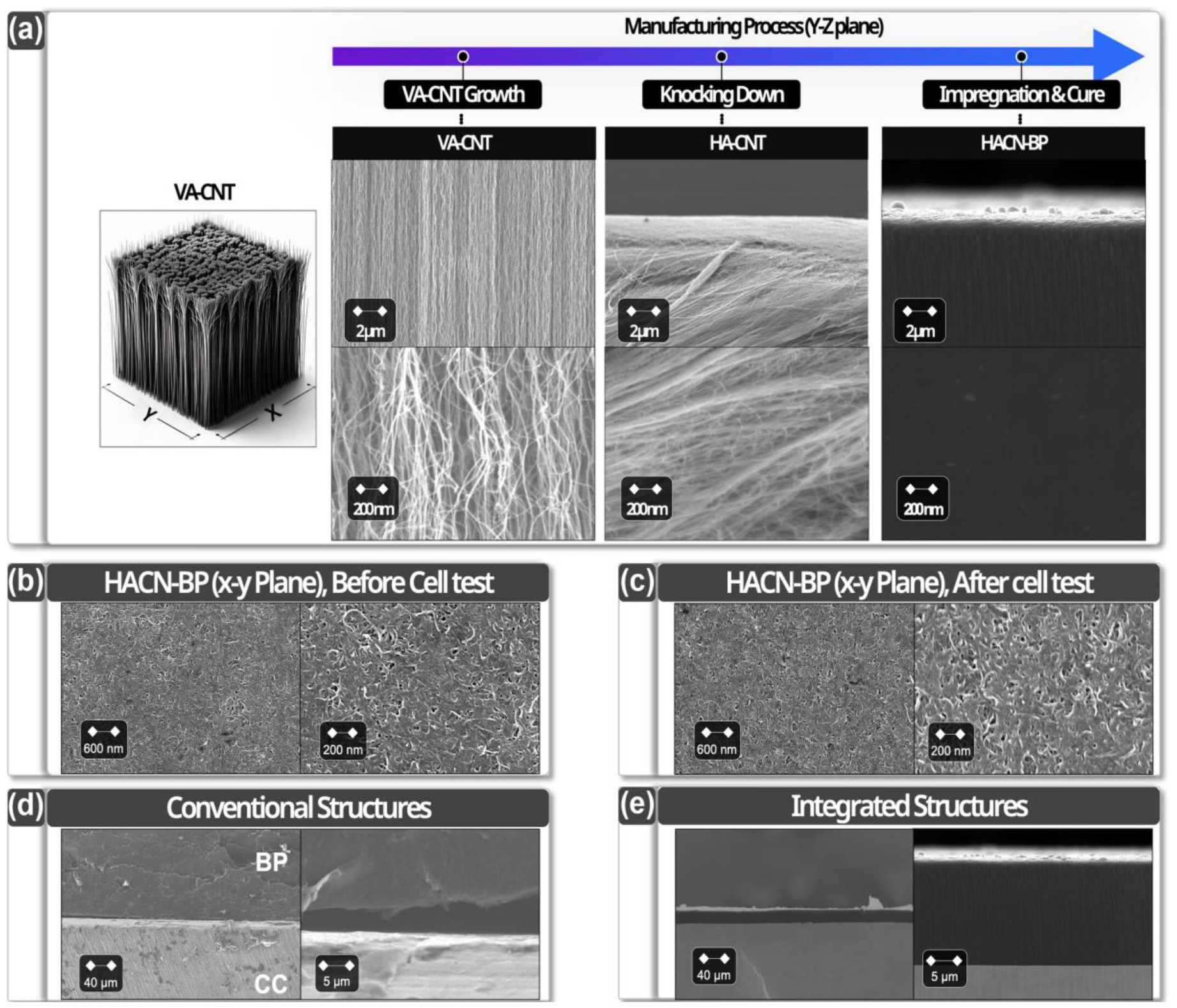
Figure 8. Surface morphology of the HACN-BP. Reprinted from Ref.[75], under CC BY 4.0 license. VA-CNT: Vertically aligned carbon nanotube; HA-CNT: horizontally aligned carbon nanotube; HACN-BP: horizontally aligned carbon nanotube /epoxy nanocomposite bipolar plate; CC: Current Collector.
Research trends indicate significant differences in the research focus between thermoplastic and thermosetting composite bipolar plates (CBPs). Studies on thermoplastic systems primarily concentrate on optimizing filler design, whereas those on thermosetting systems place greater emphasis on innovations in structural design. This difference primarily stems from the fundamentally distinct inherent properties, interfacial behaviors, and processing constraints of the two matrix materials. Thermoplastic and thermosetting composite materials exhibit essential differences in their processing behavior that directly influence the patterns of flow field formation. Thermoplastic resins soften and flow when heated, enabling optimal mold filling and high molding efficiency. This makes them particularly suitable for replicating complex flow field geometries and ideal for continuous manufacturing processes. However, a high filler content significantly increases melt viscosity, thereby restricting fluidity and potentially leading to incomplete filling or reduced accuracy in fine flow field characteristics. In contrast, thermosetting resins undergo an irreversible curing process: their fluidity is limited during processing, but they exhibit excellent dimensional stability after curing, which helps maintain the geometric shape of the formed flow field. However, insufficient fluidity during the molding process makes precise replication of complex or micro-scale structures challenging; additionally, curing shrinkage and internal stresses may cause runner deformation or defect formation. Thermoplastic resins (such as polyvinylidene fluoride and polyetheretherketone) typically require elevated temperatures and pressures during molding, which can lead to uneven distribution of conductive fillers within the polymer melt, resulting in discontinuous conductive networks that reduce electrical conductivity and impair battery performance[74-77]. Furthermore, a significant difference may exist between the thermal expansion coefficient of thermoplastic composites and that of carbon fillers, which can easily induce interfacial micro-cracks during operating temperature cycles, thereby increasing gas permeability. Weak interfacial adhesion is another common issue, leading to a marked reduction in mechanical strength during humidity cycling - for instance, tensile strength may decrease by more than 20%[78,79]. Thermosetting resins (such as phenolic and epoxy resins) form cross-linked structures during curing, which may restrict the rearrangement and densification of conductive fillers, resulting in composite materials that still do not fully meet battery operating conductivity requirements. Although thermosetting resins generally exhibit good dimensional stability, filler orientation and segregation during injection molding can lead to anisotropic performance and batch-to-batch inconsistencies in composite bipolar plates, posing challenges to large-scale production and long-term operational reliability[80,81]. Meanwhile, shrinkage during curing may generate stress at the interface, compromising both interfacial bond strength and the material’s long-term durability. In a word, whether using thermoplastic or thermosetting resins as binders, carbon-resin composite bipolar plates face various challenges: discontinuous conductive networks, microcracks, increased gas permeability due to mismatched thermal expansion coefficients, reduced mechanical strength due to weak interfacial adhesion, and filler segregation and anisotropy during molding. These issues collectively limit their widespread application in batteries. The following Table 3 presents a summary comparison of the processability of thermoplastic and thermosetting CBP.
Comparison of formability of thermoplastic and thermosetting CBPs
| Parameter | Thermoplastic CBPs | Thermosetting CBPs |
| Typical defects | Incomplete filling, filler agglomeration, and depression marks at channel corners[37,46] | Micro-pores and brittle micro-cracks at the root of ribs[36] |
| Dimensional tolerance | High-modulus materials exhibit less rebound, whereas low-modulus materials demonstrate greater rebound. During filling[82,83] | Susceptible to overall warpage induced by thermal residual stresses from curing-induced processes[68] |
| Scalability & cycle time | Excellent (second-to-minute level, highly compatible with continuous processes)[58,82] | Moderate (minutes to hours, typically involving batch compression molding)[20,34] |
Overall, thermoplastics are limited by flowability during forming, while thermosetting systems are constrained by curing behavior. Both impose inherent constraints on the formability and manufacturability of flow field structures. The performance charts for different single battery cells are listed below, as shown in Table 4.
The efficiency of single cells in different batteries
| No. | Literature | Electrolyte [L] | Cycles | T [°C] | Electrolyte | EE [%] | CE [%] | VE [%] | Charge/discharge voltage [V] | Cell-S | Current density [mA/cm2] | Active area [cm2] |
| 1 | Nam et al.[70] | 0.05 | 20 | 84.3 | 1.2-1.6 | 1 | 60 | 4,900 | ||||
| 0.05 | 20 | 83.4 | 1.2-1.6 | 1 | 80 | 4,900 | ||||||
| 0.05 | 20 | 80.4 | 1.2-1.6 | 1 | 100 | 4,900 | ||||||
| 2 | Zhang et al.[84] | 0.1 | 112 | 25 | 1.5M Vn+ and 2M sulfate | 82 | 96 | 85 | 1 | 70 | 28 | |
| 16.5 | 2300 | 75 | 93 | 80 | 5 | 50 | 2,000 | |||||
| 3 | Choe et al.[85] | 0.05 | 1.6M vanadium ion | ~ 82 | 1.2-1.6 | 1 | 100 | |||||
| 0.05 | 1.6M vanadium ion | ~ 71 | 1.0-1.7 | 200 | ||||||||
| 4 | Lim and Lee[86] | 100 | 84 | ~ 96 | ~ 98 | 1 | ||||||
| 5 | Choe et al.[72] | 80 | ||||||||||
| 6 | Liao et al.[87] | 0.07 | 1.5M V2+ in 3.0M H2SO4, 1.5M VO2+ in 3.0M H2SO4 | 85.7 | 96.7 | 88.6 | 0.8-1.65 | 100(37.5,140) | 40 | |||
| 7 | Liao et al.[57] | 0.07 | VO2+ in 3.0M H2SO4 1.5M V2+ in 3.0 M H2SO4, 1.5M VO2+ in 3.0 M H2SO4 | 85.9 | 97.6 | 88.0 | 0.8-1.65 | 1 | 100(37.5,140) | 40 | ||
| 8 | Liu et al.[37] | 0.15 | 4 | 1.5M vanadium sulfide in 1.5M H2SO4 | ~ 72 -79 | > 80 | 1-1.55 | 1 | 40 | 24 | ||
| 9 | Yang et al.[88] | 18 | 81.61 | 96.45 | 84.61 | 1-1.7 | 1 | 80(120,160) | ||||
| 10 | Dongjiang et al.[89] | 0.05 | > 100 | 1.5M V4+ in 3M H2SO4, 1.5M V3+ in 3M H2SO4 | ~ 80 | ~ 84 | 0.8-1.75 | 1 | 50 | 10 |
Forming challenges of CBP with flow field
In RFBs, the flow field structure plays a critical role in regulating the distribution of the electrolyte within the porous electrode and the associated mass transport processes, thereby significantly influencing the battery’s power density and overall system efficiency[90]. With the increasing demand for high power density, low pressure drop, and high energy efficiency, flow field designs have gradually evolved from conventional simple serpentine or interdigitated fields toward more advanced architectures such as multi-level branching structures, biomimetic designs, and three-dimensional flow fields[28]. These complex structures can significantly improve mass transport uniformity and reactant utilization. However, they also impose stricter requirements on the geometric precision and structural consistency of the flow fields. Small deviations in field width, depth, rib-to-field ratio, and corner transition morphology can alter the local flow velocity distribution, electrode compression state, and interfacial contact resistance, ultimately affecting the overall electrochemical performance of the battery[91-93]. Therefore, the pursuit of higher performance has driven flow field structures toward increasing complexity, making high-precision forming an essential requirement. At the same time, the capabilities of manufacturing processes inherently constrain the achievable types and complexity of flow field architectures.
As structural complexity continues to increase, challenges related to forming consistency, dimensional control, interfacial integrity, and large-scale production stability become increasingly prominent. These issues pose significant barriers to the practical engineering application of CBP. Consequently, in the development of high-performance flow batteries, focusing solely on material properties or structural design is no longer sufficient. It is necessary to integrate flow field optimization with high-precision manufacturing technologies to achieve high-performance structures that are practically manufacturable.
Advances in flow field design: design ambition vs. forming reality
In conventional serpentine flow fields, insufficient convection and uneven species distribution often occur near the channel outlet and in the under-rib regions[94,95]. Lu et al. introduce a blocking structure at the bends of the serpentine field[96], thereby increasing the pressure difference beneath the ribs and promoting electrolyte penetration into the porous electrode, as shown in Figure 9.
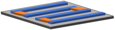
Figure 9. Illustration of the blocked serpentine flow field.
However, interdigitated flow fields are highly sensitive to pumping power and, in large-scale applications, also face a trade-off between energy consumption and structural complexity. Chai et al. introduce a parallel interdigitated flow field with a higher aspect ratio structure[91]. The parallel interdigitated structures [PIFF (T2) and PIFF (T3)] effectively increase the flow velocity beneath the ribs, thereby enhancing mass transfer between branch channels and adjacent side channels, as shown in Figure 10. These designs highlight another important trend: the transition from planar structures to more three-dimensional (3D) flow field architectures with variable rib heights and complex channel networks. However, such 3D features introduce significant challenges in pressure transfer and material flow during molding.
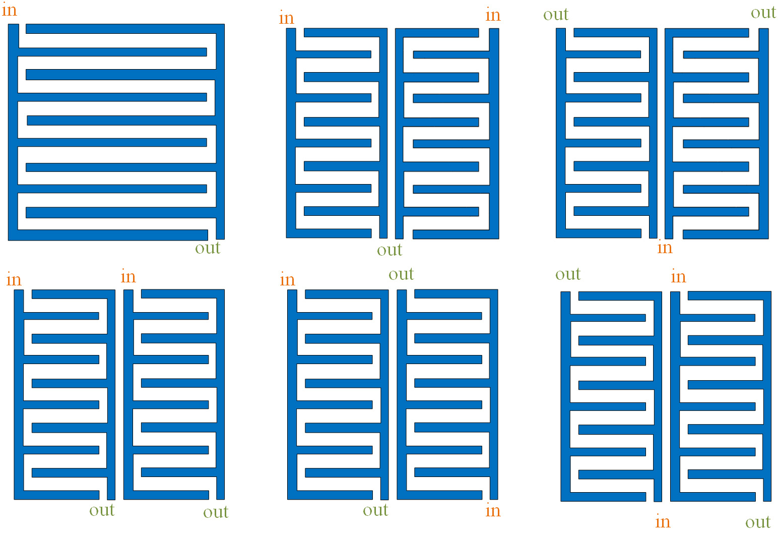
Figure 10. Schematic diagrams of different flow fields.
Although the above-modified flow fields make remarkable progress in boosting mass transfer and enhancing performance, they still face a series of challenges in forming and processing in practical engineering applications and large-scale manufacturing. The increase in the number of flow field corners and variations in rib height introduce complex geometrical features that significantly increase the processing difficulty of the plates, placing higher demands on mold precision and manufacturing consistency. For CBPs, the increasing complexity of rib width and rib height structures often leads to local stress concentration and uneven resin flow during hot pressing[97]. In addition, although parallel or bifurcated structural designs are beneficial for regulating pressure drop distribution, the fine structural features also pose challenges to mold lifetime and manufacturing cost. Meanwhile, in order to further strengthen mass transfer and control pumping power, researchers have proposed new complex flow field designs that combine obstruction structures with simulation-based optimization. For example, biomimetic flow fields inspired by plant leaf venation incorporate obstacles of different shapes (circular, diamond, and triangular)[98,99]. Others, inspired by fuel cell architectures and natural transport networks, introduce spiral or nonlinear flow paths[100,101]. These biomimetic designs represent the highest level of structural sophistication, enabling precise control over local mass transport behavior. However, they also impose the most stringent requirements on manufacturability. The presence of multi-scale features and complex curvature significantly increases the difficulty of melt filling and, more critically, mold release. In particular, undercuts, sharp angles, and intricate internal geometries can cause severe demolding resistance, leading to surface damage or structural defects during part removal. In addition, as shown in Tables 5-7, we summarized the specific flow field parameters of thermoplastic and thermosetting bipolar plates used in RFBs and Proton Exchange Membrane Fuel Cells (PEMFCs) to enable a more intuitive comparison of the challenges in flow field fabrication.
Flow field parameters of BPs based on thermoplastic resins
| Flow field parameters of BPs based on thermoplastic resins |
| Graphite/polypropylene surface layer with a flow field depth of 1 mm; the flow field width is not specified[102] |
| A polypropylene-based BP for PEMFCs with flow field dimensions of 1.5 mm in width and 0.5 mm in depth[103] |
| Different ratios of flow field width, rib width, and flow field depth were investigated, with the optimal flow field configuration identified as (5, 2, 3), applicable to VRFBs of various scales, including 416 cm2, 918 cm2, and 1,495 cm2[104] |
| A flow field bipolar plate for redox flow batteries was fabricated using polyvinyl chloride, with a channel cross-sectional area of 4 × 1.59 mm2 and a flow field pitch of 7.5 mm[105] |
| A lung-inspired biomimetic structure was fabricated using 3D printing technology, with a constant flow field depth of 0.5 mm and flow field widths varying across hierarchical levels. (1.1 mm), (1.2 mm-0.7 mm), (1.1 mm-0.7 mm-0.45 mm)[106] |
Flow field parameters of BPs based on thermosetting resins
| Flow field parameters of BPs based on thermosetting resins |
| A commercial flat-plate PEMFC bipolar plate with a designed thickness of 1.8 mm, featuring a gas flow field structure with a depth of 0.65 mm and a width of 0.5 mm[36] |
| A benzoxazine resin-based bipolar plate for PEMFC with a flow field width of 1.5 mm[107] |
| An epoxy resin-based bipolar plate for fuel cells with flow field dimensions of 1.5 mm in width and 0.3 mm in depth[108] |
| Flow fields measuring 1.1 mm × 1.8 mm were formed on a metal plate, followed by encapsulation with a carbon-polymer composite material[109] |
| An epoxy resin-based serpentine flow field bipolar plate for PEMFC with a thickness of 0.6 mm and a field depth of 1 mm[110] |
Flow field parameters of VRFB BPs
| Flow field width | Flow field depth | Rib width | Flow field types | Reference |
| 2mm | 2mm | 2mm | Serpentine flow field | [111] |
| 1mm | 4mm | 5mm | Interdigitated flow field | [112] |
| 1.5mm | 1.5mm | 2mm | Interdigitated /Serpentine flow field | [113] |
| 2mm | 2mm | 2mm | Serpentine flow field | [114] |
| 1mm | N/A | 1mm | Interdigitated /Serpentine flow field | [115] |
| 2mm | 1.4mm | N/A | Distributive interdigitated flow field | [116] |
| 2mm | 1.5mm | 2mm | Serpentine flow field | [117] |
| 4mm | 4mm | Scaled-up serpentine flow field | [118] | |
| 2mm-Main flow field 0.5mm-Secondary flow field | N/A | Vein-like flow field | [70] | |
| 3mm | 2mm | 3mm | [119] |
Flow field forming challenges
The fundamental challenge in forming flow fields in VRFB BPs is the need to simultaneously satisfy multiple functions under harsh electrochemical environments, including fluid distribution, electron conduction, and mechanical support. At present, the fabrication of flow fields in BPs mainly relies on machining and compression molding[119-121]. Machining methods typically use graphite or dense composite plates as substrates, in which the desired flow field structures are directly produced by milling or engraving. However, when fabricating fine field features in graphite materials, cutting parameters such as feed rate significantly affect surface quality and can induce surface damage. Due to the intrinsic brittleness of graphite, crack propagation and fracture are prone to occur during machining. In addition, tool deflection during micro-milling further reduces dimensional and form accuracy, leading to structural defects in fine features[103,122,123].
In contrast, compression molding integrates the flow field structure concurrently during the forming process. This approach offers potential advantages such as simplified processing steps and is therefore widely regarded as an ideal route for the large-scale manufacturing of CBPs[34].
Forming defects
Existing studies indicate that during compression molding, the material exhibits complex and constrained flow behavior due to its rheological characteristics and fiber interactions. Meanwhile, the pressure distribution within the mold cavity is often non-uniform and evolves, which can lead to defects such as voids, insufficient impregnation, and structural inhomogeneity[124,125]. More importantly, such defects act as preferential initiation sites for electrolyte penetration and localized electrochemical reactions. As a result, microcracks and interfacial gaps facilitate the ingress of acidic electrolyte, while filler agglomeration and resin-deficient regions lead to uneven current distribution.
Although fuel cells operate under relatively milder conditions and therefore face fewer challenges in flow field forming, they still encounter issues related to forming defects. Understanding these issues provides valuable insights into flow field fabrication in flow batteries. During the hot-press molding of CBPs, defects such as incomplete filling and demolding damage often occur due to restricted material flow and insufficient pressure transfer. As a result, the geometric design of flow fields must consider formability. In particular, the draft angle not only affects demolding efficiency but may also influence BP performance. Yusuf et al. report[119] that V-shaped flow fields exhibit higher forming accuracy than U-shaped flow fields with a zero draft angle [Figure 11A]. U-shaped fields require an appropriate draft angle to avoid sample fracture [Figure 11B]. It should be noted that although a larger draft angle facilitates demolding, it also tends to produce a rougher surface on the formed sample.
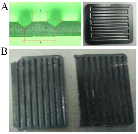
Figure 11. (A) Dimensional schematic of the V-shaped demolding design and the corresponding fabricated BP; (B) fracture of the BP sample. Reprinted from Ref.[119], under CC BY 4.0 license. BP: Bipolar plate.
Simaafrookhteh et al.point out that for thermosetting CBPs, the crosslinking reaction during hot pressing can generate water vapor or ammonia[36]. Therefore, implementing an appropriate degassing step is critical to ensuring optimal performance. In addition, the mold’s average surface temperature, surface roughness, and even the filler feeding method can influence the plate’s surface quality and the accuracy of the flow field’s forming. Furthermore, Boyacı et al. find that improper molding pressure may cause adhesion betweenthe plate and the mold surface[41], resulting in visible pores on the BP surface. Such pores act as defect sites that can facilitate electrolyte penetration and initiate localized corrosion, as shown in Figure 12.
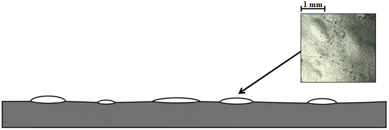
Figure 12. Surface bubble leakage caused by inappropriate molding methods.
Under optimal pressure and temperature conditions, extending the molding time can effectively reduce the surface roughness. Zhang et al. fabricate CBPs with high flow field forming accuracy and low surface roughness through a three-layer structural design[120]. Owing to the plasticity of expanded graphite, the difference between the formed field depth and the mold field depth is only ±4 μm. The specific parameters of surface roughness are shown in Table 8. Meanwhile, Zhu et al. report that the impregnating agent is primarily distributed between graphite layers and that when the plate is subjected to bending loads, stress tends to concentrate in the inclined regions of the flow field[97].
Surface roughness of the flow field under different resin contents[
| Resin content | Surface roughness Ra (μm) | Differences from molds |
| 10% | 2.411 | Maximum, approximately +1.3 μm |
| 10/20/10% | 1.582 | Low, approximately +0.48 μm |
| 20% | 1.536 | Approximately +0.43 μm |
| 30% | 1.849 | Approximately +0.74 μm |
Therefore, the interfacial bonding between the resin and graphite layers, as well as the uniformity and degree of crosslinking in the impregnated resin distribution, are key factors determining the compressive performance of flow field-containing BPs. Poor interfacial bonding or non-uniform resin distribution can lead to microcrack initiation in flow field regions. These defects may propagate under cyclic loading and electrolyte exposure, thereby accelerating localized corrosion and structural degradation. Table 9 lists the main challenges in forming flow fields.
Summary of the main challenges in runner forming
| Reference | Key innovation | Main conclusions |
| Sepehr et al.[36] | Multi-filler thermoset composite BP; improved conductivity (~ 38 S/cm) and strength (47 MPa); defect mitigation strategy | Molding defects are critical; precise fields (0.5 mm × 0.65 mm) are achievable only with defect control |
| Zhu et al.[97] | Ultra-thin flexible BP (0.775 mm); wettability regulation for enhanced performance | Field wettability dominates water management and mass transport behavior |
| Yusuf et al.[119] | Direct flow-field fabrication via hot compression; optimized V-shaped field | Dimensional precision deviation (~ -0.118% to 0.27%); geometry affects demolding and manufacturability |
For CBPs with flow fields attached on both sides, the fabrication process also faces significant challenges. To address this issue, Brent proposes two manufacturing approaches[126]. The flow fields are first fabricated separately[34], after which the mold is rotated by 90°. The two halves of the BP are then heated and fused to form the final plate. In the second method, one side of the plate is first molded. The half plate is then flipped, and the flow field is molded on the other side to produce the final BP. The manufacturing process is shown in Figure 13.
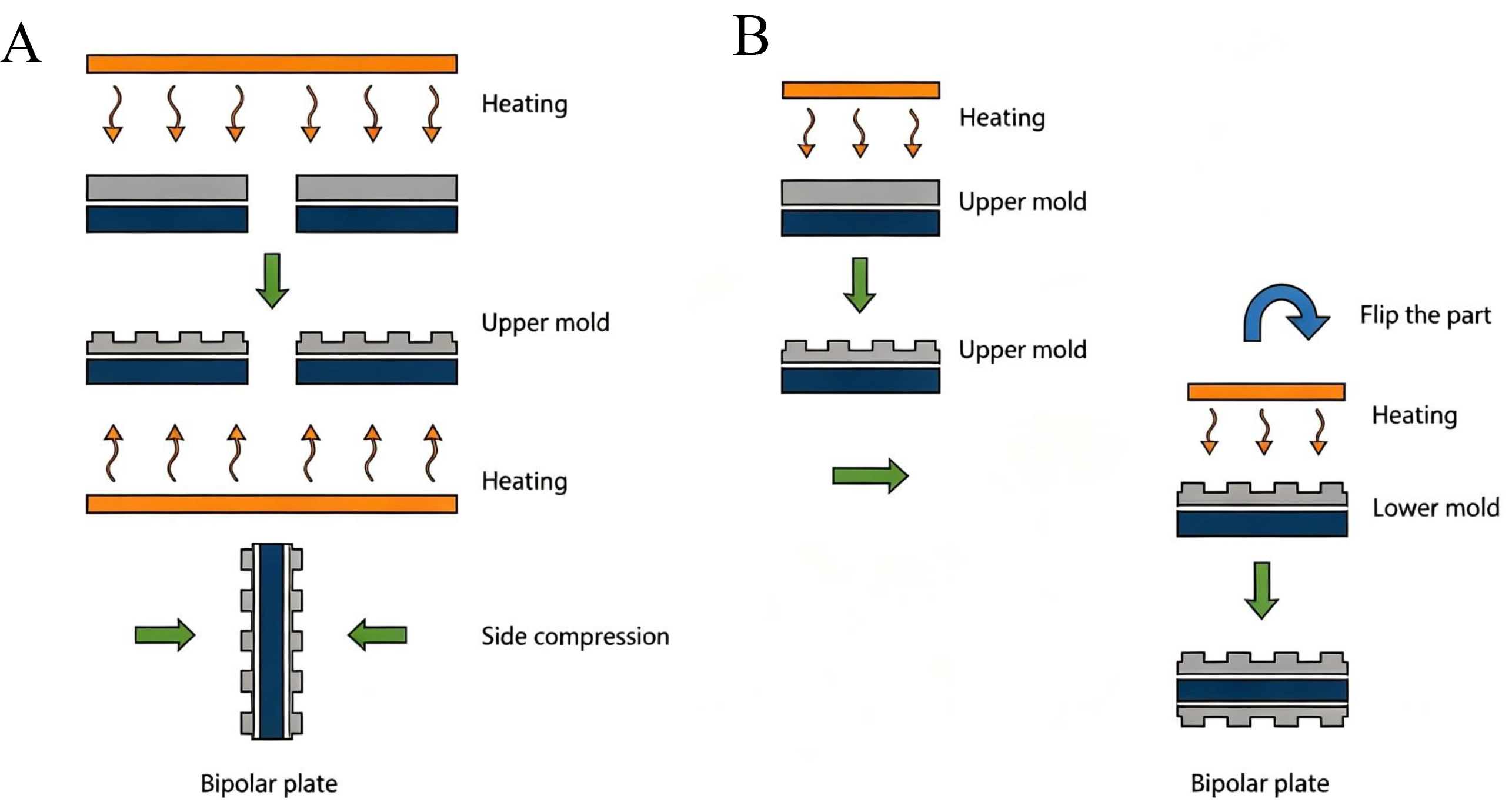
Figure 13. Schematic diagram of flow field bipolar plate formation (A) Both parts of the BP are formed simultaneously; (B) The two parts of the BP are formed sequentially. BP: Bipolar plate.
Accurately evaluating the severity of forming defects is essential. The conventional performance targets for bipolar plates require an area-specific resistance (ASR) < 0.4 Ω·cm2 and a flexural strength > 40 MPa. The critical defect size threshold determines the plate’s feasibility. Sietmann et al. indicate that the presence of the flow field structure itself increases the resistance of the BP by approximately 19% compared with that of a solid bulk material. In contrast, internal defects increase the overall resistance by only about 1%-4%[37]. However, macroscopic defects (> 0.5 mm), such as incomplete rib filling, can significantly impair mechanical integrity and alter local pressure drop[127]. More critically, surface cracks wider than 50 μm or sharp corners formed during defect formation can serve as pathways for acidic electrolyte penetration, thereby greatly accelerating galvanostatic corrosion and active-species degradation at defect sites[128-130]. The characteristics of the corrosion morphology are shown in Figure 14.
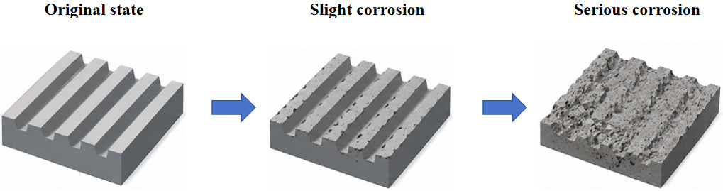
Figure 14. Corrosion morphology characteristics of bipolar plates with flow fields after a certain number of cycles.
Therefore, quality control in flow field fabrication must strictly limit surface cracks to < 50 μm and suppress internal pore agglomeration to maintain flexural strength and electrochemical stability[72,131] simultaneously.
The effect of small random particles is almost negligible. Therefore, from the perspective of electrical performance, the geometry of the flow fields has a much greater impact on resistance than internal micro-defects. Nevertheless, for structural reliability and long-term operational stability, greater attention should be paid to large defects such as cracks, bubbles, and pore agglomerations. In terms of quality control, millimeter-scale defects can be identified through Computed Tomography (CT) inspection, without excessive concern about the influence of micron-scale dispersed particles on electrical conductivity[37].
Electrochemical corrosion and chemical corrosion
As mentioned above, BPs used in flow batteries must operate in strongly acidic and highly oxidative environments. Therefore, the fabrication of flow fields must not only consider the impact of forming defects but also account for their long-term stability in harsh corrosive environments. During corrosion, both the stability and electrical conductivity of the BP may deteriorate. In addition, parasitic reactions that consume electrons during corrosion can reduce battery efficiency and capacity. The corrosion of CBPs in VRFBs can generally be classified into two types: electrochemical corrosion and chemical corrosion[20,132].
Fundamentally, both originate from carbon oxidation driven by the combined effects of high potential on the positive electrode and a strongly acidic vanadium electrolyte. Electrochemical corrosion is the most common corrosion mechanism. However, the standard potential for carbon corrosion is 0.207 V, which is lower than the anode potential of VRFBs; therefore, the BP on the cathode side usually exhibits relatively high stability[51,129]. During the corrosion process, carbon-oxygen-containing functional groups such as C-O, C=O, and O-C-O are formed[130] rather than being released directly as gases. These oxygen-containing functional groups increase surface hydrophilicity. They also facilitate the penetration of electrolytes into internal defects of the plate. Because the diffusion of reactive ions within cracks and pores is limited, a higher overpotential is required, which accelerates the conversion of these oxygen-containing functional groups into CO or CO2[133]. Continuous penetration and corrosion may subsequently lead to plate cracking and even cause internal short circuits in the battery. For CBPs with flow fields, the fields and their adjacent regions are prone to local potentials significantly higher than the average. After 120 charge-discharge cycles, additional active sites tend to form at the edges and corners of the flow fields, where oxidation reactions lead to further loss of carbon atoms[131]. In addition, the degradation of the ribs in the flow field may also intensify the non-uniform distribution of potential, resulting in locally elevated potentials that further accelerate the electrochemical oxidation process. Clearly shows the cross-sectional morphology of the corroded region[128]. The bright corroded areas exhibit a more open structure, which increases the likelihood of electrolyte penetrating through the plate. Moreover, obvious carbon black agglomerations can be observed in the non-corroded regions (yellow arrow areas), whereas no identifiable carbon black is found in the corroded regions. This suggests that carbon black particles may participate in the corrosion reaction more actively than graphite. These findings indicate that although the geometry of the flow fields accounts for a major portion of the resistance in BPs, unthinkingly reducing resistance by adding more conductive particles may instead increase the risk of corrosion.
The chemical corrosion of bipolar plates in flow batteries primarily results from direct chemical attack by active substances in the electrolyte on the plate materials. For example, in vanadium redox flow batteries (VRFBs), the high-concentration sulfuric acid electrolyte serves as the primary corrosive agent[134]. The strongly acidic environment of sulfuric acid solution can directly attack the carbon materials on the bipolar plate surface, leading to the oxidation of C-C and C=C bonds within the carbon framework. Furthermore, the active vanadium ions in the electrolyte, particularly in highly oxidized states [such as vanadium(V)], exhibit strong oxidizing properties that can chemically react directly with the carbon materials of bipolar plates, leading to oxidative degradation. In composite bipolar plates, the interface between the polymer matrix (e.g., phenolic resin, polyanthraquinone) and the conductive fillers (e.g., graphite, carbon fiber) represents a vulnerable site for chemical corrosion[81]. The electrolyte may penetrate these interfaces, attacking the polymer matrix or fillers, thereby reducing interfacial adhesion and compromising the material’s structural integrity. Prolonged immersion in corrosive electrolytes may also cause swelling, dissolution, or degradation of the polymer matrix, adversely affecting its mechanical properties and dimensional stability. Compared with electrochemical corrosion, this type of corrosion is significantly milder[134]. Even after 190 days of immersion in a fully charged electrolyte (100% state of charge), scanning electron microscopy revealed no observable changes in the composite bipolar plate. However, if a metal is inserted between the bipolar plates, surface corrosion may subsequently lead to electrochemical corrosion of the metal[135].
Outlook on flow field forming challenges
In recent years, numerous novel flow field structures have been proposed using computational fluid dynamics (CFD), topology optimization, and data-driven design methods[111,114,136]. These designs often demonstrate significantly improved uniformity of electrolyte distribution and mass-transfer performance in simulations. However, they face considerable challenges in practical fabrication. First, complex flow fields typically exhibit highly differentiated geometric features, whereas compression molding relies on the restricted flow of materials under high temperature and pressure. In composite systems with high filler content, it is difficult for the material to fill fine grooves and intricate structures fully. Second, complex flow fields often lack properly designed draft angles, making it inevitable for the demolding process to introduce edge damage and microcracks. As a result, the development of new fabrication approaches is urgently required to accommodate the increasingly sophisticated flow field structures.
CONCLUSION AND OUTLOOK
CBPs are formed by combining conductive carbon materials with a polymer matrix. They achieve a good balance among electrical conductivity, corrosion resistance, mechanical strength, and processability. Therefore, they have become an important research focus for flow battery BPs in recent years. The incorporation of flow fields enables significant performance enhancement of RFB stacks at relatively low cost. However, the continuous increase in flow field complexity inevitably exacerbates the manufacturing challenges of BPs with integrated flow fields.
Meanwhile, the performance requirements for redox flow batteries (RFBs) continue to rise. Consequently, flow field structure design has emerged as a key strategy for enhancing battery stack performance. However, while complex flow field configurations improve battery performance, they also impose higher demands on the molding process of CBPs (composite bipolar plates). In practical manufacturing and operation, these plates face dual challenges of molding accuracy and long-term corrosion resistance. Different resin systems and molding parameters significantly affect the molding accuracy of the flow field; during compression molding, the normal stress on the flow field ribs is much lower than the shear stress generated by friction, resulting in a substantially lower filler density in the ribs compared to the ridges. Moreover, the ribs are frequently subjected to electrolyte erosion during battery operation, necessitating higher material density and lower defect density. Furthermore, compared to flow-field-free bipolar plates, the ridges of flow-field bipolar plates also serve an electron exchange function. This enables higher current density to be achieved within a smaller area, but it readily leads to localized excessive overpotential, resulting in corrosion and failure of the conductive filler. In summary, ensuring precise distribution of fillers and pressure to the rib ridges during the molding process remains a key focus for future research. CBP materials must operate continuously in highly acidic electrolytes; damage to the flow field regions along the ribs or planar surfaces increases the risk of battery stack failure. Thermosetting resins undergo three-dimensional cross-linking and curing reactions during compression molding, enabling high-precision replication of complex flow fields while maintaining excellent dimensional stability. In contrast, although thermoplastic CBP offers higher processing efficiency, the high filler loading significantly reduces melt fluidity. It limits the material’s ability to conform to flow patterns at the microscopic scale, making it more suitable for relatively simple flow configurations or large-scale sheet production. Looking forward, three critical forming challenges will dominate future research in CBPs with integrated flow fields:
(1) Defect mitigation: Suppressing voids, resin-rich regions, and fiber/filler segregation during molding remains essential to ensure both mechanical reliability and corrosion resistance.
(2) Precision scale-up: Achieving uniform, high-resolution replication of complex flow fields over large-area plates is a key barrier to industrialization, requiring advances in mold design, pressure distribution control and process stability.
(3) Material flow modeling: Developing accurate multi-scale models that capture the rheological behavior of highly filled composites during molding is crucial for predicting flow, optimizing process parameters and guiding material design.
These challenges are strongly coupled with material choices and structural design strategies. Therefore, future progress will rely on the co-optimization of materials, flow field design, and forming processes, rather than isolated improvements in a single dimension.
DECLARATIONS
Authors’ contributions
Methodology, software, investigation, writing original draft: Guo, Q.
Validation, formal analysis, visualization: Sun, H.
Conceptualization, writing review and data curation: Li, J.
Writing review, editing and supervision: Wang, H.
Writing review, discussion, project administration and resources: Ma, X.
Availability of data and materials
Not applicable.
AI and AI-assisted tools statement
During the preparation of this manuscript, the AI tool Gemini 3.5 Flash (version 3.5 Flash, released 2026-05-19) was used solely for language editing. The tool did not influence the study design, data collection, analysis, interpretation, or the scientific content of the work. All authors take full responsibility for the accuracy, integrity, and final content of the manuscript.
Financial support and sponsorship
This research was supported by the Science and Technology Major Project of Liaoning Province (Grant No. 2024JH1/11700011).
Conflicts of interest
All authors declared that there are no conflicts of interest.
Ethical approval and consent to participate
Not applicable.
Consent for publication
Not applicable.
Copyright
© The Author(s) 2026.
REFERENCES
1. Hu, H.; Han, M.; Liu, J.; et al. Strategies for improving the design of porous fiber felt electrodes for all-vanadium redox flow batteries from macro and micro perspectives. Energy. Environ. Sci. 2025, 18, 3085-119.
2. Rahman, A.; Farrok, O.; Haque, M. M. Environmental impact of renewable energy source based electrical power plants: solar, wind, hydroelectric, biomass, geothermal, tidal, ocean, and osmotic. Renew. Sust. Energ. Rev. 2022, 161, 112279.
3. Dinesh, A.; Olivera, S.; Venkatesh, K.; et al. Iron-based flow batteries to store renewable energies. Environ. Chem. Lett. 2018, 16, 683-94.
4. Yuan, J.; Pan, Z.; Jin, Y.; et al. Membranes in non-aqueous redox flow battery: a review. J. Power. Sources. 2021, 500, 229983.
5. Yu, Z.; Jia, X.; Cai, Y.; et al. Electrolyte engineering for efficient and stable vanadium redox flow batteries. Energy. Storage. Mater. 2024, 69, 103404.
6. Yuan, Z.; Li, X. Perspective of alkaline zinc-based flow batteries. Sci. China. Chem. 2022, 67, 260-75.
7. Poudel, M. B.; Anand, R.; Ojha, G. P.; et al. Nitrogen coordinated atomically dispersed manganese catalyzes oxygen reduction in practical zinc-air batteries and alkaline fuel cells. J. Power. Sources. 2026, 678, 239959.
8. Ramasamy, S. K.; Mannu, P.; Backiyaleela, S. S. V.; et al. Re, Ru, and Rh (RRR) catalysts in sustainable hydrogen production via urea-assisted water electrolysis. Chem. Eng. J. 2025, 522, 167201.
9. Raihan, M. A.; Dyker, C. A. Status and prospects for symmetric organic redox flow batteries. J. Energy. Chem. 2025, 100, 125-43.
10. Lei, T.; Xu, Y.; Li, Y.; et al. Recent advances in all-iron flow batteries (AIFBs). Curr. Opin. Electroche. 2025, 52, 101702.
11. Zhao, Y.; Zheng, M. Battery management system for zinc-based flow batteries: a review. Renew. Sust. Energ. Rev. 2025, 215, 115604.
12. Tang, L.; Lu, W.; Li, X. Electrolytes for bromine-based flow batteries: challenges, strategies, and prospects. Energy. Storage. Mater. 2024, 70, 103532.
13. Shoaib, M.; Vallayil, P.; Jaiswal, N.; et al. Advances in redox flow batteries - a comprehensive review on inorganic and organic electrolytes and engineering perspectives. Adv. Energy. Mater. 2024, 14, 2400721.
14. Lourenssen, K.; Williams, J.; Ahmadpour, F.; Clemmer, R.; Tasnim, S. Vanadium redox flow batteries: a comprehensive review. J. Energy. Storage. 2019, 25, 100844.
15. Zhang, H.; Sun, C. Cost-effective iron-based aqueous redox flow batteries for large-scale energy storage application: A review. J. Power. Sources. 2021, 493, 229445.
16. Zhang, H.; Lu, W.; Li, X. Progress and perspectives of flow battery technologies. Electrochem. Energ. Rev. 2019, 2, 492-506.
17. Pilonetto, L. F.; Staciaki, F.; Nóbrega, E.; Carneiro-Neto, E. B.; Da Silva, J.; Pereira, E. Mitigating the capacity loss by crossover transport in vanadium redox flow battery: a chemometric efficient strategy proposed using finite element method simulation. Chem. Eng. J. 2023, 474, 145336.
18. Yuan, Z.; Liang, L.; Dai, Q.; et al. Low-cost hydrocarbon membrane enables commercial-scale flow batteries for long-duration energy storage. Joule 2022, 6, 884-905.
19. Fan, D.; Gong, J.; Deng, S.; Yan, H.; Zhu, Q.; Jiang, H. Progress and challenges of zinciodine flow batteries: From energy storage mechanism to key components. J. Energy. Storage. 2024, 92, 112215.
20. Satola, B. Review - bipolar plates for the vanadium redox flow battery. J. Electrochem. Soc. 2021, 168, 060503.
21. Kumar, S.; Jayanti, S. Effect of flow field on the performance of an all-vanadium redox flow battery. J. Power. Sources. 2016, 307, 782-7.
22. Wlodarczyk, R.; Zasada, D.; Morel, S.; Kacprzak, A. A comparison of nickel coated and uncoated sintered stainless steel used as bipolar plates in low-temperature fuel cells. Int. J. Hydrogen. Energy. 2016, 41, 17644-51.
23. Reynard, D.; Vrubel, H.; Dennison, C. R.; Battistel, A.; Girault, H. On-site purification of copper-contaminated vanadium electrolytes by using a vanadium redox flow battery. ChemSusChem 2019, 12, 1222-8.
24. Novalin, T.; Eriksson, B.; Proch, S.; et al. Concepts for preventing metal dissolution from stainless-steel bipolar plates in PEM fuel cells. Energy. Convers. Manage. 2022, 253, 115153.
25. Shen, S.; Lin, Z.; Song, K.; et al. Reversed active sites boost the intrinsic activity of graphene-like cobalt selenide for hydrogen evolution. Angew. Chem. Int. Ed. 2021, 60, 12360-5.
26. Liu, H.; Cai, T.; Song, Q.; Yang, L.; Xu, Q.; Yan, C. Electrochemical behavior of the titanium plate with carbon films in a vanadium sulfate solution. Int. J. Electrochem. Sci. 2013, 8, 2515-23.
27. Han, J.; Yoo, H.; Kim, M.; Lee, G.; Choi, J. High-performance bipolar plate of thin IrOx -coated TiO2 nanotubes in vanadium redox flow batteries. Catal. Today. 2017, 295, 132-9.
28. Gautam, R. K.; Kumar, A. A review of bipolar plate materials and flow field designs in the all-vanadium redox flow battery. J. Energy. Storage. 2022, 48, 104003.
29. Dihrab, S. S.; Sopian, K.; Alghoul, M.; Sulaiman, M. Review of the membrane and bipolar plates materials for conventional and unitized regenerative fuel cells. Renew. Sust. Energ. Rev. 2009, 13, 1663-8.
30. Yen, C.; Liao, S.; Lin, Y.; Hung, C.; Lin, Y.; Ma, C. M. Preparation and properties of high performance nanocomposite bipolar plate for fuel cell. J. Power. Sources. 2006, 162, 309-15.
31. Hanapi, I. H.; Kamarudin, S. K.; Beygisangchin, M.; et al. Review of recent composite bipolar plate in system development. J. Environ. Chem. Eng. 2024, 12, 113776.
32. Ke, X.; Prahl, J. M.; Alexander, J. I. D.; Wainright, J. S.; Zawodzinski, T. A.; Savinell, R. F. Rechargeable redox flow batteries: flow fields, stacks and design considerations. Chem. Soc. Rev. 2018, 47, 8721-43.
33. Lu, M.; Yin, C.; Ma, Q.; et al. Flow field structure design for redox flow battery: Developments and Prospects. J. Energy. Storage. 2024, 95, 112303.
34. Alo, O. A.; Otunniyi, I. O.; Sadiku, E. R. Processing methods for conductive polymer composite bipolar plates: effect on plate quality and performance. Fuel. Cells. 2023, 23, 136-60.
35. Karumbaiah, K. M.; Kracke, C.; Battley, M.; Bickerton, S.; Allen, T. Damage assessment of carbon-epoxy composites with and without resin flow channels. Compos. Struct. 2019, 211, 213-20.
36. Simaafrookhteh, S.; Khorshidian, M.; Momenifar, M. Fabrication of multi-filler thermoset-based composite bipolar plates for PEMFCs applications: molding defects and properties characterizations. Int. J. Hydrogen. Energy. 2020, 45, 14119-32.
37. Sietmann, M.; Janßen, H.; Müller, M.; Lehnert, W. An analysis of the imperfections and defects inside composite bipolar plates using X-ray computer tomography and resistivity simulations. Int. J. Hydrogen. Energy. 2021, 46, 25677-88.
38. Goudarzi, R.; Hashemi Motlagh, G. Relationship between pore structure with residual pore and mechanical properties of expanded graphite nanocomposites at varying molding pressures. J. Appl. Polym. Sci. 2021, 138, 50994.
39. Liu, Z.; Wang, B.; Yu, L. Preparation and surface modification of PVDF-carbon felt composite bipolar plates for vanadium flow battery. J. Energy. Chem. 2018, 27, 1369-75.
40. Park, H.; Woo, J. S.; Park, S. Poly(phenylene sulfide)-graphite composites for bipolar plates with preferred morphological orientation. Korean. J. Chem. Eng. 2019, 36, 2133-42.
41. Boyacı San, F. G.; Okur, O. The effect of compression molding parameters on the electrical and physical properties of polymer composite bipolar plates. Int. J. Hydrogen. Energy. 2017, 42, 23054-69.
42. Zheng, J.; Peng, Y.; Fan, R.; et al. Study on carbon matrix composite bipolar plates with balance of conductivity and flexural strength. Chin. Chem. Lett. 2023, 34, 107616.
43. Boyaci San, F. G.; Tekin, G. A review of thermoplastic composites for bipolar plate applications: thermoplastic composites for bipolar plate. Int. J. Energy. Res. 2013, 37, 283-309.
44. Yao, S.; Jin, F.; Rhee, K. Y.; Hui, D.; Park, S. Recent advances in carbon-fiber-reinforced thermoplastic composites: a review. Compos. Part. B-Eng. 2018, 142, 241-50.
45. Zhou, P.; Tian, J.; Li, C.; Tang, Z. Comparative study of durability behaviors of thermoplastic polypropylene and thermosetting epoxy exposed to elevated temperature, water immersion and sustained bending loading. Polymers 2022, 14, 2953.
46. Mighri, F.; Huneault, M. A.; Champagne, M. F. Electrically conductive thermoplastic blends for injection and compression molding of bipolar plates in the fuel cell application. Polym. Eng. Sci. 2004, 44, 1755-65.
47. Hodgkin, J. H.; Simon, G. P.; Varley, R. J. Thermoplastic toughening of epoxy resins: a critical review. Polym. Adv. Technol. 1998, 9, 3-10.
48. Luo, T.; Ma, Y.; Cui, X. Review on frontal polymerization behavior for thermosetting resins: materials, modeling and application. Polymers 2024, 16, 185.
49. Liu, T.; Zhao, B.; Zhang, J. Recent development of repairable, malleable and recyclable thermosetting polymers through dynamic transesterification. Polymer 2020, 194, 122392.
50. Hsiao, M.; Liao, S.; Yen, M.; et al. Effect of graphite sizes and carbon nanotubes content on flowability of bulk-molding compound and formability of the composite bipolar plate for fuel cell. J. Power. Sources. 2010, 195, 5645-50.
51. Duan, Z.; Qu, Z.; Ren, Q.; Zhang, J. Review of bipolar plate in redox flow batteries: materials, structures, and manufacturing. Electrochem. Energy. Rev. 2021, 4, 718-56.
52. Zan, R.; Hao, B.; Tao, Z.; et al. Research on the flexibility of composite bipolar plate materials. Diamond. Relat. Mater. 2026, 161, 113127.
53. Kim, S.; Yoon, Y.; Narejo, G. M.; Jung, M.; Kim, K. J.; Kim, Y. J. Flexible graphite bipolar plates for vanadium redox flow batteries. Int. J. Energy. Res. 2021, 45, 11098-108.
54. Kang, Y.; Zhang, H.; Weng, Y.; et al. Modification of graphite-based composite bipolar plates by “nanoglue” strategy for vanadium redox flow battery. Carbon. Lett. 2025, 35, 1589-97.
55. Akhtar, M. N.; Sulong, A. B.; Umer, A.; Yousaf, A. B.; Khan, M. A. Multi-component MWCNT/NG/EP-based bipolar plates with enhanced mechanical and electrical characteristics fabricated by compression moulding. Ceram. Int. 2018, 44, 14457-64.
56. Hanapi, I. H.; Kamarudin, S. K.; Zainoodin, A. M.; et al. Electrical conductivity enhancement of chopped carbon fiber‐reinforced epoxy composite bipolar plate for proton exchange membrane fuel cells. J. Appl. Polym. Sci. 2024, 142, e56421.
57. Liao, W.; Jiang, F.; Zhang, Y.; Zhou, X.; He, Z. Highly-conductive composite bipolar plate based on ternary carbon materials and its performance in redox flow batteries. Renew. Energ. 2020, 152, 1310-6.
58. Manzoor, A. T.; Tomer, V. K.; Garmabi, M. M.; et al. Progress and perspective on thermoplastic composites for hydrogen fuel cells. Chem. Eng. J. 2025, 515, 163795.
59. Jiang, F.; Liao, W.; Ayukawa, T.; Yoon, S.; Nakabayashi, K.; Miyawaki, J. Enhanced performance and durability of composite bipolar plate with surface modification of cactus-like carbon nanofibers. J. Power. Sources. 2021, 482, 228903.
60. Qin, Y.; Liu, J.; Han, Y.; et al. Constructing high-performance composite bipolar plates via multidimensional carbon networks. Polym. Compos. 2025, 46, S964-72.
61. Zhang, J.; Zhou, T.; Xia, L.; Yuan, C.; Zhang, W.; Zhang, A. Polypropylene elastomer composite for the all-vanadium redox flow battery: current collector materials. J. Mater. Chem. A. 2015, 3, 2387-98.
62. Meng, X.; Li, C.; Fan, R.; Zheng, J.; Ming, P. Catalytic curing-driven ultrafast fabrication of high-density composite bipolar plates for PEMFCs. Chin. Chem. Lett. 2025, 111480.
63. Onyu, K.; Yeetsorn, R.; Gostick, J. Fabrication of bipolar plates from thermoplastic elastomer composites for vanadium redox flow battery. Polymers 2022, 14, 2143.
64. Loktionov, P.; Kartashova, N.; Konev, D.; et al. Fluoropolymer impregnated graphite foil as a bipolar plates of vanadium flow battery. Int. J. Energy. Res. 2021, 46, 10123-32.
65. Li, W.; Jing, S.; Wang, S.; Wang, C.; Xie, X. Experimental investigation of expanded graphite/phenolic resin composite bipolar plate. Int. J. Hydrogen. Energy. 2016, 41, 16240-6.
66. Choe, J.; Woo Lim, J. Conductive nanoparticle-embedded carbon composite bipolar plates for vanadium redox flow batteries. Compos. Struct. 2024, 329, 117770.
67. Kim, K. H.; Choe, J.; Nam, S.; Kim, B. G.; Lee, D. G. Surface crack closing method for the carbon composite bipolar plates of a redox flow battery. Compos. Struct. 2015, 119, 436-42.
68. Soohyun, N.; Dongyoung, L.; Ilbeom, C.; Dai Gil, L. Smart cure cycle for reducing the thermal residual stress of a co-cured E-glass/carbon/epoxy composite structure for a vanadium redox flow battery. Compos. Struct. 2015, 120, 107-16.
69. Lee, D.; Lim, J. W.; Nam, S.; Choi, I.; Lee, D. G. Method for exposing carbon fibers on composite bipolar plates. Compos. Struct. 2015, 134, 1-9.
70. Nam, S.; Lee, D.; Lee, D. G.; Kim, J. Nano carbon/fluoroelastomer composite bipolar plate for a vanadium redox flow battery (VRFB). Compos. Struct. 2017, 159, 220-7.
71. Lee, D.; Choe, J.; Nam, S.; Lim, J. W.; Choi, I.; Lee, D. G. Development of non-woven carbon felt composite bipolar plates using the soft layer method. Compos. Struct. 2017, 160, 976-82.
72. Choe, J.; Lim, J. W.; Kim, M.; Kim, J.; Lee, D. G. Durability of graphite coated carbon composite bipolar plates for vanadium redox flow batteries. Compos. Struct. 2015, 134, 106-13.
73. Choe, J.; Lim, J. W. Carbon-composite bipolar plate-integrated current collector for vanadium redox flow battery. J. Power. Sources. 2024, 589, 233751.
74. Choe, J.; Lee, D.; Yoon On, S.; Su Kim, S.; Woo Lim, J. Development of a spread-tow fabric composite bipolar plate with fiber-spreading effect for vanadium redox flow battery. Compos. Part. A-Appl. S. 2024, 176, 107878.
75. Jeong, J. M.; Dai, J.; Acauan, L.; et al. Aligned carbon nanotube polymer nanocomposite bipolar plates technology for vanadium redox flow batteries. Energy. Environ. Mater. 2025, 8, e70030.
76. Li, W.; Zeng, H.; Xie, Z. Preparation and properties and performance study of chopped carbon fiber/polyvinylidene fluoride/expanded graphite composite bipolar plates utilizing surface-coated carbon nanotubes. J. Solid. State. Electrochem. 2024, 29, 1611-21.
77. Zeng, H.; Li, W.; Zhu, Z.; Wu, Y.; Pan, X.; Xie, Z. Structural and performance investigation of hydroxylated carbon nanotube/expanded graphite/ carboxylated poly(ether ether ketone) composite bipolar plates for PEMFC. Int. J. Hydrogen. Energy. 2026, 200, 152148.
78. Li, W.; Zhao, Y.; Pan, X.; Liu, M.; Qiu, S.; Xie, Z. Structure and properties of carboxylated carbon nanotubes@expanded graphite/polyethersulfone composite bipolar plates for PEM. Nanomaterials 2023, 13, 2055.
79. Dai, H.; Zhang, C.; Lu, Y. Carbon fiber fabric/graphite reinforced polyphenylene sulfide composite for fuel cell bipolar plates. Polym. Compos. 2025, 46, S694-704.
80. Xu, G.; Du, X.; Chang, L.; Hu, X.; Song, J. Effect of molding temperature on the properties of phenolic resin/carbon black/graphite composite bipolar plates. J. Solid. State. Electrochem. 2024, 28, 2505-13.
81. Zhou, S.; Mao, X.; Hu, X.; et al. Multi-performance synergistic optimization of sandwich-structured composite bipolar plates based on polyaniline/carbon nanotubes@nickel foam. Polym. Compos. 2025, 47, 6512-26.
82. Yeetsorn, R.; Fowler, M.; Tzoganakis, C. A review of thermoplastic composites for bipolar plate materials in PEM fuel cells. In: Nanocomposites with unique properties and applications in medicine and industry; IntechOpen: London, 2011; pp 317-344.
83. Chang, C.; Chou, H.; Hsu, N.; Chen, Y. Development of integrally molded bipolar plates for all-vanadium redox flow batteries. Energies 2016, 9, 350.
84. Zhang, J.; Zhou, T.; Xia, L.; Yuan, C.; Zhang, W.; Zhang, A. Polypropylene elastomer composite for the all-vanadium redox flow battery: current collector materials. J. Mater. Chem. A. 2015, 3, 2387-98.
85. Choe, J.; Kim, J.; Lee, D. G. Shape optimization of the corrugated composite bipolar plate (CCBP) for vanadium redox flow batteries (VRFBs). Compos. Struct. 2016, 158, 333-9.
86. Lim, J. W.; Lee, D. G. Carbon fiber/polyethylene bipolar plate-carbon felt electrode assembly for vanadium redox flow batteries (VRFB). Compos. Struct. 2015, 134, 483-92.
87. Liao, W.; Zhang, Y.; Zhou, X.; et al. Low-carbon-content composite bipolar plates: a novel design and its performance in vanadium redox flow batteries. Chem. Select. 2019, 4, 2421-7.
88. Yang, L.; Zhou, Y.; Wang, S.; Lin, Y.; Huang, T.; Yu, A. A novel bipolar plate design for vanadium redox flow battery application. Int. J. Electrochem. Sci. 2017, 12, 7031-8.
89. Dongjiang, Y.; Jingyuan, L.; Litao, K. High‐temperature conductive binder for an integrated electrode bipolar plate and its application in vanadium redox flow battery. Int. J. Energy. Res. 2019, 44, 1920-9.
90. Hao, H.; Zhang, Q.; Feng, Z.; Tang, A. Regulating flow field design on carbon felt electrode towards high power density operation of vanadium flow batteries. Chem. Eng. J. 2022, 450, 138170.
91. Chai, Y.; Qu, D.; Fan, L.; Zheng, Y.; Yang, F. A parallel interdigitated flow field with higher aspect ratio for enhancing the performance of vanadium redox flow batteries. Journal. of. Energy. Storage. 2024, 97, 112800.
92. Sun, J.; Liu, B.; Zheng, M.; Luo, Y.; Yu, Z. Serpentine flow field with changing rib width for enhancing electrolyte penetration uniformity in redox flow batteries. J. Energy. Storage. 2022, 49, 104135.
93. Pan, L.; Sun, J.; Qi, H.; et al. Along-flow-path gradient flow field enabling uniform distributions of reactants for redox flow batteries. J. Power. Sources. 2023, 570, 233012.
94. Ali, E.; Kwon, H.; Kim, J.; Park, H. Numerical study on serpentine design flow channel configurations for vanadium redox flow batteries. J. Energy. Storage. 2020, 32, 101802.
95. Wang, Y.; Li, M.; Hao, L. Three-dimensional modeling study of all-vanadium redox flow batteries with the serpentine and interdigitated flow fields. J. Electroanal. Chem. 2022, 918, 116460.
96. Lu, M.; Jiao, Y.; Tang, X.; Yang, W.; Ye, M.; Xu, Q. Blocked serpentine flow field with enhanced species transport and improved flow distribution for vanadium redox flow battery. J. Energy. Storage. 2021, 35, 102284.
97. Zhu, C.; Zhang, Y.; Huang, X.; et al. The ultra-thin flexible graphite/epoxy bipolar plates adjusted by different surface tension modifiers and application in the fuel cell stack. Int. J. Hydrogen. Energy. 2024, 79, 1347-56.
98. Liu, Y.; Huang, Z.; Xie, X.; et al. Redox flow battery:Flow field design based on bionic mechanism with different obstructions. Chem. Eng. J. 2024, 498, 155663.
99. Huang, Z.; Liu, Y.; Xie, X.; et al. Design and optimization of a novel flow field structure to improve the comprehensive performance of vanadium redox flow batteries. J. Power. Sources. 2025, 640, 236736.
100. Chai, Y.; Qu, D.; Fan, L.; Zheng, Y.; Yang, F. A double-spiral flow channel of vanadium redox flow batteries for enhancing mass transfer and reducing pressure drop. J. Energy. Storage. 2024, 78, 110278.
101. Yaji, K.; Yamasaki, S.; Tsushima, S.; Suzuki, T.; Fujita, K. Topology optimization for the design of flow fields in a redox flow battery. Struct. Multidisc. Optim. 2017, 57, 535-46.
102. Lee, Y.; Lee, C.; Kim, K.; Lim, D. Preparation and properties on the graphite/polypropylene composite bipolar plates with a 304 stainless steel by compression molding for PEM fuel cell. Int. J. Hydrogen. Energy. 2011, 36, 7621-7.
103. Huo, D.; Lin, C.; Dalgarno, K. An experimental investigation on micro machining of fine-grained graphite. Int. J. Adv. Manuf. Technol. 2014, 72, 943-53.
104. Gundlapalli, R.; Jayanti, S. Dataset on performance of large-scale vanadium redox flow batteries with serpentine flow fields. Data. in. Brief. 2021, 35, 106835.
105. Al-Yasiri, M.; Park, J. A novel cell design of vanadium redox flow batteries for enhancing energy and power performance. Appl. Energy. 2018, 222, 530-9.
106. Muñoz-Perales, V.; Van Der Heijden, M.; García-Salaberri, P. A.; Vera, M.; Forner-cuenca, A. Engineering lung-inspired flow field geometries for electrochemical flow cells with stereolithography 3D printing. ACS. Sustainable. Chem. Eng. 2023, 11, 12243-55.
107. Huang, Q.; Tong, Y.; Hu, B.; et al. High-performance polybenzoxazine based composites PEMFC bipolar plates with a multi-layer structure for surface enrichment of conductive phase. Int. J. Hydrogen. Energy. 2023, 48, 32540-52.
108. Kim, S. O.; Kim, S. Y.; Kim, M. Improving the electrical performance of a carbon fiber reinforced polymer bipolar plate using a resin squeeze-out preprocess. Compos. Commun. 2022, 32, 101156.
109. Choi, H.; Seo, D. J.; Choi, W. Y.; et al. An ultralight-weight polymer electrolyte fuel cell based on woven carbon fiber-resin reinforced bipolar plate. J. Power. Sources. 2021, 484, 229291.
110. Kang, K.; Park, S.; Jo, A.; Lee, K.; Ju, H. Development of ultralight and thin bipolar plates using epoxy-carbon fiber prepregs and graphite composites. Int. J. Hydrogen. Energy. 2017, 42, 1691-7.
111. Yang, W.; Zhang, R.; Lu, M.; Lin, Y.; Liang, L.; Xu, Q. Novel flow field design for redox flow battery using algorithmic channel generation and self-adaptive network model and experimental verification. Chem. Eng. J. 2024, 499, 156346.
112. Wu, T.; Huang, Y.; Xu, B. Flow field-electrode coordination in vanadium redox flow batteries: Balancing hydraulic loss and active area through embedded flow field designs. J. Energy. Storage. 2026, 149, 120030.
113. Wu, T.; Huang, Y.; Fei, Y.; Chen, X.; Xu, B. Study on the effects of electrode fiber and flow channel arrangements on mass transfer and electrochemical performance of vanadium redox flow batteries. Energy 2024, 313, 133900.
114. Wan, S.; Jiang, H.; Guo, Z.; et al. Machine learning-assisted design of flow fields for redox flow batteries. Energy. Environ. Sci. 2022, 15, 2874-88.
115. Guo, Z.; Wang, Z.; Sun, J.; et al. Hydrodynamic analysis of scaling-up flow fields for redox flow batteries using a macro-segment network model. Chem. Eng. J. 2025, 519, 165206.
116. Zhou, Z.; Yang, X.; Zheng, N.; Sun, Z. Numerical investigations of scalable loop-type flow fields with enhanced convective mass transfer for vanadium redox flow batteries. J. Power. Sources. 2026, 666, 239182.
117. Guo, Z.; Ren, J.; Sun, J.; et al. A split convection-enhanced flow field for stack-scale redox flow batteries. Chem. Eng. J. 2025, 511, 161937.
118. Ren, J.; Guo, Z.; Wang, Y.; et al. A convection-enhanced flow field with height-changing ribs for redox flow batteries. Chem. Eng. J. 2024, 500, 157008.
119. Yusuf, M. M.; Selamat, M.; Sahari, J.; Daud, M. M.; Tahir, M. M.; Hamdan, H. Fabrication of a flow channel for the production of polymer composite bipolar plates through hot compression molding. J. Mech. Eng. Sci. 2017, 11, 2428-42.
120. Zhang, X.; Huang, H.; Fan, J.; et al. Gradient structured composite bipolar plates for proton exchange membrane fuel cells. ACS. Sustainable. Chem. Eng. 2022, 10, 15846-56.
121. Lisboa, K. M.; Marschewski, J.; Ebejer, N.; et al. Mass transport enhancement in redox flow batteries with corrugated fluidic networks. J. Power. Sources. 2017, 359, 322-31.
122. Piao, Y.; Wang, S.; Balint, D.; Giuliani, F.; Saiz, E.; Gavalda-Diaz, O. Deformation and toughening of graphite at the micron scale. Acta. Mater. 2025, 299, 121428.
123. Hascelik, A.; Aslantas, K. Minimisation of micro-wall deformation through variable feed rate technique in micro-milling operations. J. Manuf. Process. 2025, 149, 770-84.
124. Chen, C.; Young, W. The Effects of Compression pressure on injection compression molding. Int. Polym. Process. 2022, 15, 176-9.
125. Ma, Y.; Li, S.; Wang, J.; Ju, L.; Liu, X. Influence of defects on bending properties of 2D-T700/E44 composites prepared by improved compression molding process. Materials 2018, 11, 2132.
126. Cunningham, B.D. The development of compression moldable polymer composite bipolar plates for fuel cells. Ph.D. Dissertation, Virginia Tech, Blacksburg, VA, 2007.
127. Ahmed, R.; Sharma, S.; Dhandapani, S.; et al. Bipolar plate flow channel designs for vanadium redox flow battery: a review. J. Power. Sources. 2026, 665, 239101.
128. Sharma, P.; Bilican, A.; Schmidt, W.; et al. Navigating harsh ageing: Unraveling galvanostatic corrosion effects on different constituents of carbon-polymer composite bipolar plates for vanadium redox flow batteries. Carbon 2024, 221, 118907.
129. Oreiro, S. N.; Jacquemond, R. R.; Boz, E. B.; Forner-cuenca, A.; Bentien, A. Investigation of the positive electrode and bipolar plate degradation in vanadium redox flow batteries. J. Energy. Storage. 2025, 132, 117689.
130. Duan, Z.; Qu, Z.; Wang, Q.; Wang, J. Structural modification of vanadium redox flow battery with high electrochemical corrosion resistance. Appl. Energy. 2019, 250, 1632-40.
131. Gupta, G.; Satola, B.; Komsiyska, L.; Harms, C.; Hickmann, T.; Dyck, A. electrochemical aging and characterization of graphite-polymer based composite bipolar plates for vanadium redox flow batteries. J. Electrochem. Soc. 2022, 169, 080503.
132. Rudolph, S.; Schröder, U.; Bayanov, I.; Pfeiffer, G. Corrosion prevention of graphite collector in vanadium redox flow battery. J. Electroanal. Chem. 2013, 709, 93-8.
133. Liu, H.; Yang, L.; Xu, Q.; Yan, C. Corrosion behavior of a bipolar plate of carbon-polythene composite in a vanadium redox flow battery. RSC. Adv. 2015, 5, 5928-32.
134. Pezeshki, A. M.; Sacci, R. L.; Veith, G. M.; Zawodzinski, T. A.; Mench, M. M. The cell-in-series method: a technique for accelerated electrode degradation in redox flow batteries. J. Electrochem. Soc. 2016, 163, A5202-10.
135. Satola, B.; Kirchner, C. N.; Komsiyska, L.; Wittstock, G. Chemical stability of graphite-polypropylene bipolar plates for the vanadium redox flow battery at resting state. J. Electrochem. Soc. 2016, 163, A2318-25.
Cite This Article
 Open Access
How to Cite
Download Citation
Export Citation File:
Type of Import
Tips on Downloading Citation
Citation Manager File Format
Type of Import
Direct Import: When the Direct Import option is selected (the default state), a dialogue box will give you the option to Save or Open the downloaded citation data. Choosing Open will either launch your citation manager or give you a choice of applications with which to use the metadata. The Save option saves the file locally for later use.
Indirect Import: When the Indirect Import option is selected, the metadata is displayed and may be copied and pasted as needed.
About This Article
Copyright

Data & Comments
Data
0











Comments
Comments must be written in English. Spam, offensive content, impersonation, and private information will not be permitted. If any comment is reported and identified as inappropriate content by OAE staff, the comment will be removed without notice. If you have any queries or need any help, please contact us at [email protected].