


Gradient engineering in proton exchange membrane fuel cell cathodes: an electrochemical study of charge transfer, mass transport, and Pt utilization
 0
0 Abstract
This study addresses a key research gap in proton exchange membrane fuel cell development by first establishing a pre-optimized non-graded catalyst layer as a reference, enabling a clearer understanding of performance improvements achieved through structural optimization. The reference catalyst layer was tuned for ionomer content and distribution, providing a high-performing baseline. Building on this, we systematically introduced through-plane gradients in Pt/C loading, ionomer-to-carbon ratio, and ionomer equivalent weight, both individually and in combination. Electrochemical impedance spectroscopy was used to unravel the underlying transport and kinetic effects. The fully graded catalyst showed a 32% performance increase at 0.6 V (humid conditions) and a 17% gain at 0.3 V (dry conditions) compared to the pre-optimized reference. These gains result from improved catalyst utilization near the membrane, enhanced gas diffusion and water management near the gas diffusion layer, and balanced ionic conductivity across the catalyst layer. The findings highlight the critical importance of combining a robust baseline optimization with rational gradient design, offering a comprehensive path to improve performance while minimizing precious metal usage. While structural factors are known to influence catalyst layer performance, this study focuses specifically on electrochemical behavior to provide detailed insights into compositional gradient effects.
Keywords
INTRODUCTION
Proton exchange membrane fuel cells (PEMFCs) have attracted considerable interest due to their high energy conversion efficiency, fast start-up capability at low temperatures, environmental compatibility, and zero local pollutant emissions. These devices can directly convert the chemical energy of hydrogen into electricity, with water as the sole byproduct, positioning them as a promising clean energy technology[1].
At the core of a PEMFC lies the membrane electrode assembly (MEA), which consists of a proton exchange membrane (PEM), catalyst layers (CLs), and gas diffusion layers (GDLs). The CLs are primarily made of platinum nanoparticles supported on carbon particles and an ionomer. The ionomer plays a crucial role within the CL, providing proton conduction pathways, contributing to structural stability, and facilitating interfacial reactions. One of the major challenges in commercializing PEMFCs lies in their reliance on expensive noble metal catalysts, which are not only costly but also problematic due to limited long-term and activity stability. These issues are exacerbated by corrosion of the carbon support and the leaching of active noble metal nanoparticles[1].
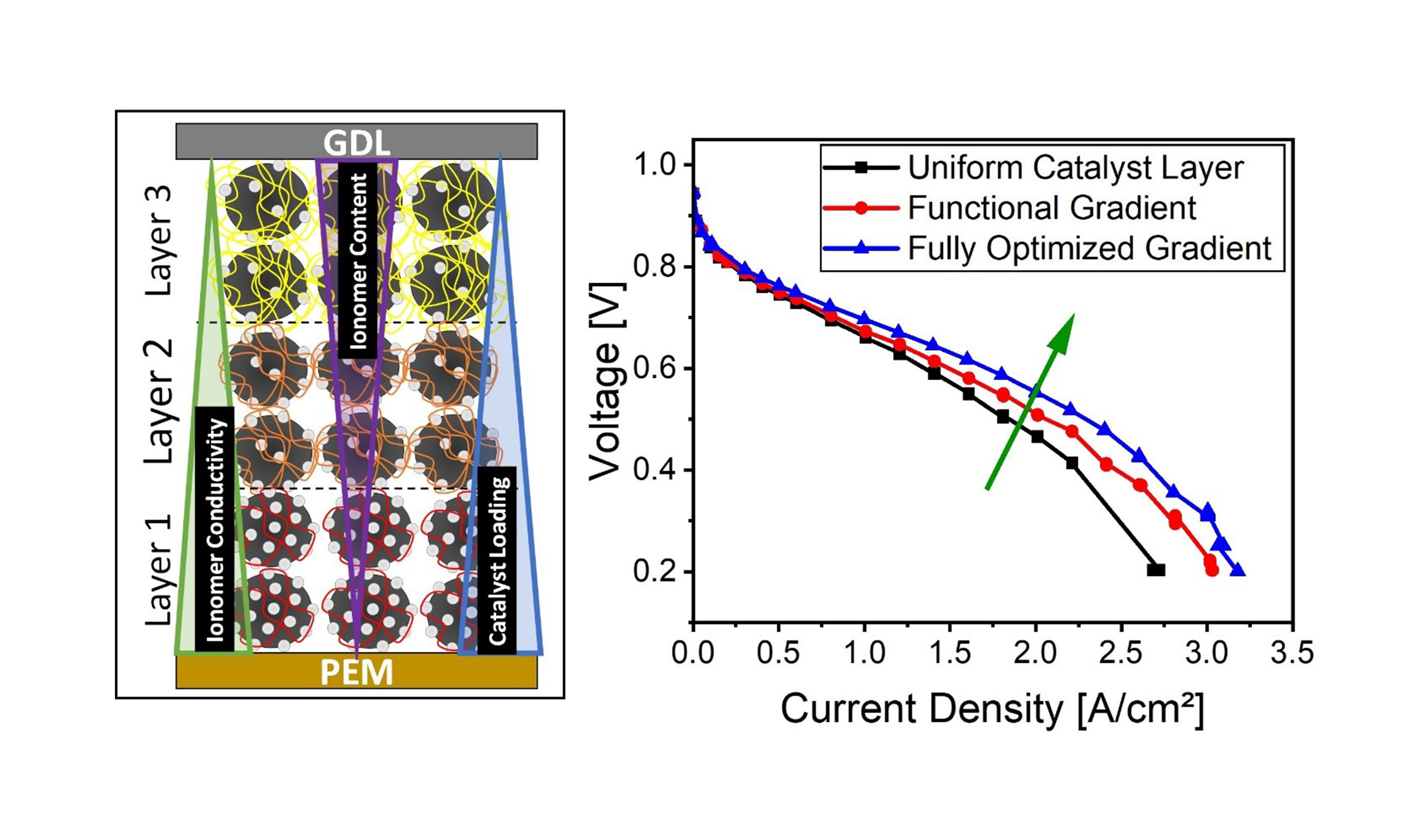
On the cathode side, a high platinum content is indispensable, as the oxygen reduction reaction (ORR) exhibits very slow kinetics[2]. This electrochemical process represents the most time- and cost-critical step in electrochemical energy conversion. Consequently, the design of CLs with optimized structures that maximize platinum and ionomer utilization, while expanding the three-phase boundary, is essential for achieving superior fuel cell performance. A key approach to improving ORR kinetics is to increase the number of accessible active catalyst sites, typically achieved by a high surface coverage of platinum. However, this leads to higher costs and an increased demand for scarce raw materials. In recent years, graded CLs have gained significant attention in PEMFCs for their potential to improve fuel cell performance by optimizing key parameters like ionomer-to-carbon (I/C) ratio, platinum-loading (Pt/C), and ionomer equivalent weight (EW), the latest refers to the weight of polymer per mole of functional group (-SO3H in this case). The optimization of these parameters through graded distributions within the CL can enhance proton conductivity, platinum utilization, and mass transport.
The fundamental motivation for these designs lies in the intrinsic spatial inhomogeneity of the ORR within the CL. During fuel cell operation, concentration gradients of reactants and products arise due to mass transport limitations, leading to non-uniform utilization of active catalytic sites. This results in local variations in reaction rate, current density, and ultimately affects overall cell performance and durability[3] [see Figure 1].
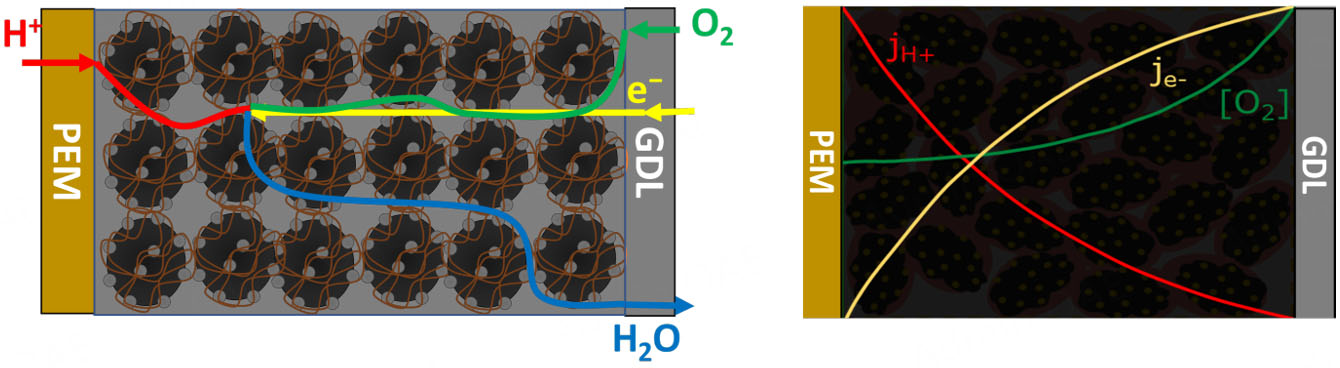
Figure 1. Schematic of the ORR spatial variation in the cathode CL. Right-hand graphic adapted from[3] with permission from Elsevier.
Graded structures, implemented by varying the I/C ratio, Pt/C loading, or ionomer EW across the through-plane direction, are specifically designed to mitigate these challenges. By tailoring the local composition along the depth of the CL, it is possible to optimize oxygen and proton transport, improve water management, and adapt the local reaction environment to the operating conditions. This can lead to more uniform current distribution, enhanced catalyst utilization, and prolonged cell lifetime.
Both numerical and experimental studies, as comprehensively reviewed in the work of Ayoub et al., have shown that the reaction rate within the CL is inherently non-uniform[4]. Graded CLs, by introducing composition variations (e.g., in Pt/C loading, I/C ratio or EW), represent a promising strategy to address this inhomogeneity. Numerous studies have investigated the effect of through-plane gradient CLs using both experimental and numerical approaches. These efforts can be categorized as follows:
Catalyst gradient: Experimental studies have demonstrated that tailoring the spatial distribution of Pt/C loading can improve mass transport and Pt utilization[5-9]. Complementary numerical modeling has been used to optimize these gradients and predict their effect on current density distribution and efficiency[6,10-13].
Ionomer gradient: Experimental investigations into I/C ratio or EW gradients have shown potential for improved water balance and ionic conductivity[14-17]. These are supported by simulation-based studies evaluating the impact of through-plane ionomer distribution on transport and electrochemical behavior[18].
Combined catalyst and ionomer gradient: A number of experimental studies have explored multilayer CLs with simultaneous gradients in Pt/C loading and ionomer content[2,19-22]. Modeling efforts in this category assess the synergy between electronic, ionic, and mass transport in co-graded architectures[23-27].
Machine learning and AI-based approaches: More recently, data-driven methods, particularly artificial neural networks and machine learning, have been applied to design and predict optimal graded structures[28-30].
However, while previous studies have explored the effects of I/C ratio, ionomer EW, and Pt/C loading within CLs to enhance PEMFC performance, a fundamental aspect has been largely overlooked: the necessity of a systematic pre-optimization tailored to the specific physicochemical properties of each catalyst material.
In the current literature, CL optimizations are commonly conducted based on the assumption that catalysts labeled similarly (e.g., Pt/C 40 wt%) exhibit comparable behavior. However, our prior study[31] investigating the physicochemical properties of various carbon blacks and their associated Pt/C catalysts has demonstrated that significant differences, such as electrical conductivity, surface hydrophilicity/hydrophobicity, and oxygen containing surface groups, arise due to varying material properties caused by diverse manufacturing and synthesis processes. These differences can profoundly influence the processing of such materials during MEA manufacturing and hence influence CL behavior, particularly in terms of ionomer-catalyst interactions, mass transport, and electrochemical activity[31]. Consequently, optimization strategies developed for one Pt/C catalyst cannot be directly transferred to other catalysts, even when they have nominally identical compositions. Without a material-specific pre-optimization, the effects of subsequent gradient strategies may be misinterpreted or significantly less effective. Moreover, industrial application remains hindered by the lack of systematic, performance-driven optimization strategies that consider the specific physicochemical properties of each catalyst material. In particular, there is a critical gap in the understanding of how I/C, EW, and Pt/C loading composition gradients should be tailored for individual catalyst types and under varying fuel cell operating conditions. Given the inherent complexity and limited fundamental insight into CL behavior, many industrial processes still rely on standard or empirically derived formulations without pre-optimization, which can result in suboptimal performance, higher material costs, and inefficient Pt utilization. In addition, to the best of the authors’ knowledge, no studies have yet investigated the effects of simultaneously grading the I/C ratio, ionomer EW, and Pt/C loading on PEMFC performance.
In this work, we address these knowledge gaps by first systematically optimizing the I/C ratio and ionomer EW for each catalyst individually, using ungraded CLs as a baseline, and customizing gradient designs to enhance performance under both high humidity and high stoichiometry and dry cathode and low stoichiometry conditions, and to also enable a more cost-effective utilization of expensive components such as ionomers and platinum. This approach ensures that the observed performance enhancements are truly due to the applied gradients and not confounded by underlying, unoptimized material behaviors. By doing so, this study provides a rigorous and transferable framework for CL optimization that accounts for intrinsic material variability, a necessary step that has been missing in previous research. Although the structure-property relationships in CLs are recognized as crucial performance drivers and have been widely reported in literature[5,8,14,32,33], the present work deliberately focuses on the electrochemical processes within graded CLs. By isolating these aspects, we aim to deepen the understanding of how compositional gradients impact charge and mass transport phenomena.
MATERIALS AND METHODS
Materials
In this experimental investigation, commercially available Pt/C catalysts and ionomers commonly used in PEMFC applications were selected. Table 1 summarizes the essential properties of the studied materials, including the type of carbon support, platinum loading, and ionomer EW, providing a detailed overview of the set of materials used. It is important to note that all materials were analyzed as received, without any additional pretreatment steps, ensuring that the results reflect the intrinsic properties of the commercial products.
Properties of materials used in this study, including ionomer EWs, Pt/C loadings, and carbon support characteristics
| Material | Abbreviation | Support | Pt-Loading [wt%] | Surface Area [m2/g] | EW [g/mol] | Supplier |
| Pt/Medium Surface Area Carbon (MSAC) | Pt/MSAC | MSAC | 40 | 145a | - | Heraeus |
| Pt/XC72R (TEC10V30E) | TKK30 | XC72R | 30 | 156b | - | Tanaka |
| Pt/XC72R (TEC10V40E) | TKK40 | XC72R | 40 | 125b | - | Tanaka |
| Pt/XC72R (TEC10V50E) | TKK50 | XC72R | 50 | 106b | - | Tanaka |
| Aquivion® D98-25BS | EW980 | - | - | - | 980 | Solvay S.A |
| Aquivion® D83-24B | EW830 | - | - | - | 830 | Solvay S.A |
| Aquivion® D72-25BS | EW720 | - | - | - | 720 | Solvay S.A |
In addition to the catalysts, deionized water, isopropanol with a purity of 99.9%, a poly(tetrafluoroethylene) (PTFE) foil with a thickness of 200 μm as a decal-substrate for the spraying process, and Nafion® HP as a membrane and a GDL (H23C9; Freudenberg) were used.
Methods
MEA Manufacturing: The Pt/C catalysts were first dispersed in a mixture of Milli-Q water, 2-propanol, and ionomer solution. This dispersion underwent initial sonication in an ultrasonic bath (45 kHz) for 30 min to ensure proper mixing. To further enhance the dispersion quality, it was subsequently treated using a sonotrode (Sonifier SFX550) operating at a frequency of 20 kHz with 10% intensity for 12 min. The resulting homogeneous suspension was then fed into an ultrasonic spray system (Sonotek). A 200 µm thick PTFE foil served as the substrate for coating, with the dispersion sprayed at a flow rate of 0.6 mL/min over a surface area of 39.7 cm2. During the spraying process, the CLs were deposited on the PTFE foil and simultaneously dried using a heating plate set to 150 °C. The CLs were designed to achieve a target platinum loading of 0.18 mgPt/cm2, which was confirmed both gravimetrically and, on a sampling basis, via micro
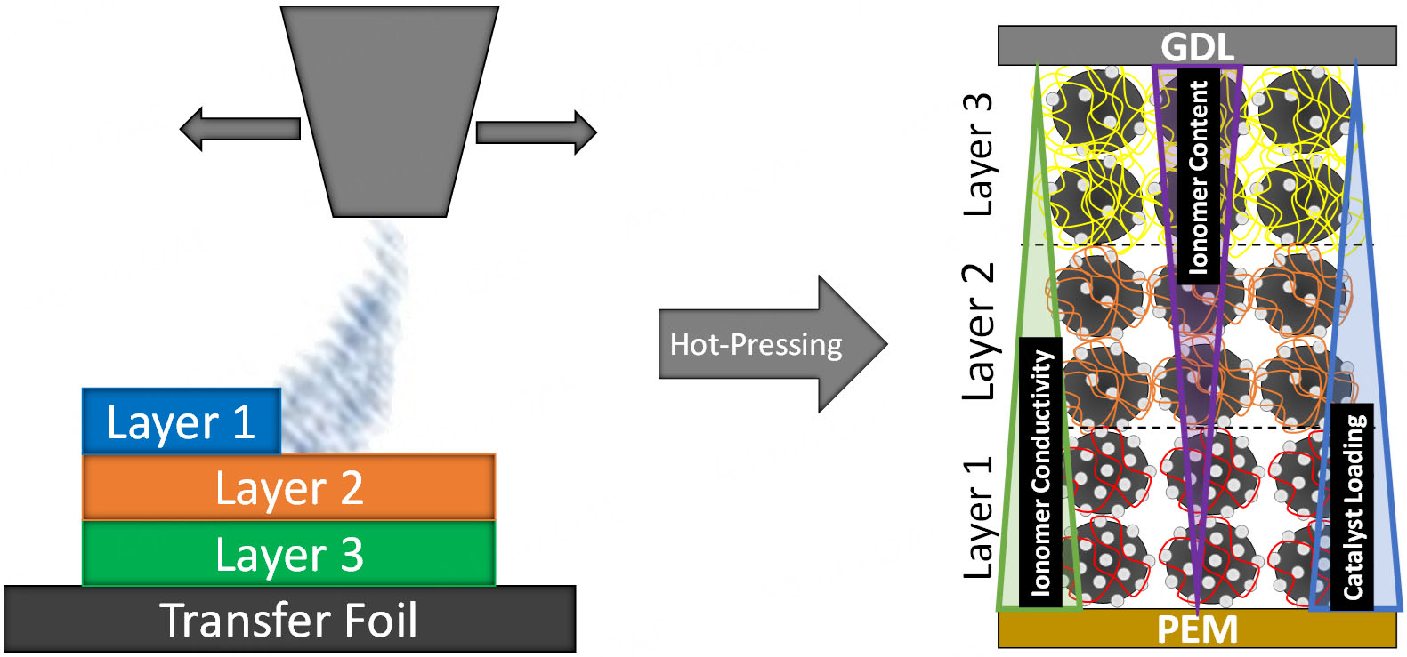
Figure 2. Layer-by-layer concept used in our gradient fabrication approach (three-layer structure).
Electrochemical in-situ Characterization: the performance and durability of each MEA were evaluated using a 25 cm2 single-cell setup (BalticFuelCells GmbH). All tests were conducted at a cell and gas inlet temperature of 80 °C under a total system pressure of 2.5 bar. Electrochemical measurements were carried out using a Zennium electrochemical workstation equipped with a PP201 potentiostat and an EL300 electronic load (Zahner-Elektrik GmbH & Co. KG). Polarization curves and electrochemical impedance spectroscopy (EIS) measurements were performed under the following defined operating conditions. The equivalent circuit model for EIS analysis and an example of fitting data are provided in
• Pol 1: Hydrogen and air were supplied at an air stoichiometry of 5 on both the anode and cathode sides. The relative humidity was set to 70% on both the anode and cathode sides, representing a moderately humidified and balanced operating condition.
• Pol 2: A more demanding test for PEMFC than Pol 1 was conducted at an air stoichiometry of 2. The anode was humidified at 70% relative humidity, while the cathode was operated without external humidification conditions (0% relative humidity; dry), simulating typical water-limited scenarios that are relevant for high current density operation and automotive applications.
Table 2 summarizes key parameters for fuel cell configuration and operating conditions.
Key parameters for fuel cell configuration and operating conditions
| Parameter | Specification |
| Pt loading | Reference CL: 0.18 mgPt/cm2; Graded CLs: 3 sub-layers of 0.06 mgPt/cm2 each |
| Active area | 25 cm2 |
| Cell type | Single cell |
| Flow-field configuration | Counter-flow; Serpentine design with 5 channels (Design of ZBT GmbH) |
| Operating conditions - Pol 1 | H2/air with stoichiometry of 5 (anode and cathode); 70% relative humidity at both anode and cathode |
| Operating conditions - Pol 2 | H2/air with stoichiometry of 5 (anode) and 2 (cathode); 70% relative humidity at the anode; 0% at the cathode |
EIS measurements were performed under two operating regimes: Pol 1 and Pol 2. However, for the analysis of resistive contributions based on equivalent circuit modeling, only EIS data from Pol 1 conditions were evaluated and discussed in the main manuscript. This decision was made in recognition of the limitations of the employed equivalent circuit [Supplementary Figure 2] under Pol 2 conditions. At these conditions, the low-frequency arc of the impedance spectra is primarily influenced by the non-uniform oxygen distribution along the cathode flow field, rather than by oxygen transport through the CL itself. Modeling such effects requires channel-level transport elements or spatially resolved diagnostics, which were not available in our experimental configuration. Therefore, fitting the spectra using the same equivalent circuit used for Pol 1 would lead to inaccurate or misleading interpretations.
While advanced techniques such as the Distribution of Relaxation Times (DRT) could potentially provide deeper insights, their application requires high-resolution spectra across a broad frequency range. Given the dynamically constrained nature of the Pol 2 measurements, we opted not to pursue DRT analysis in this case.
To maintain methodological consistency and model validity, only the impedance data from Pol 1 conditions were analyzed and interpreted. Nonetheless, the polarization curves under Pol 2 are provided in the Supplementary Figures 4-29 to enable qualitative assessment of the gradient performance under more application-relevant, mass-transport-limited conditions.
To evaluate the stability of the graded CLs under realistic operating stress, additional wet/dry cycling tests (0%-100% relative humidity at 80 °C) were conducted. The results confirm that the performance remains stable over 100 cycles, indicating robust structural and electrochemical durability
To assess whether additional interfacial resistance arises from the layer-by-layer spray deposition in the graded CLs, a comparative performance study was conducted against a single-layer reference CL with identical composition. Under Pol 1 conditions, the graded CL showed slightly reduced performance, which may be attributed to interlayer contact resistance or discontinuities in ionic/electronic pathways. Interestingly, under Pol 2 conditions, the graded CL matched the performance of the single-layer reference
RESULTS AND DISCUSSION
This study presents the optimization and grading of CLs in PEMFCs. We begin with a pre-optimization phase, investigating the effects of I/C ratio and ionomer EW using Pt/XC72R and Pt/MSAC to identify optimal parameters for ungraded CLs. These insights formed the basis for designing graded CLs, focusing on Pt/XC72R as the model catalyst.
Performance was evaluated through polarization curves under two conditions: high stoichiometry/high humidity (Pol 1) and low stoichiometry/dry (Pol 2). EIS measurements at 1 A/cm2 complemented the analysis. Current densities at 0.6 V were used for comparison, while full polarization curves are available in the
Pre-optimization of CLs (ungraded layers)
To identify optimal catalyst and ionomer combinations for the graded CL, a comprehensive pre-optimization study was conducted. This study systematically evaluated different Pt/C loadings and I/C ratios in ungraded layers. The detailed results, including current density and EIS analysis, are provided in Supplementary Figure 32, Supplementary Tables 1 and 2.
Based on these findings, a current density map was generated (see Figure 3) to visualize performance trends across the tested parameter space and to guide the final gradient layer design. In this map:
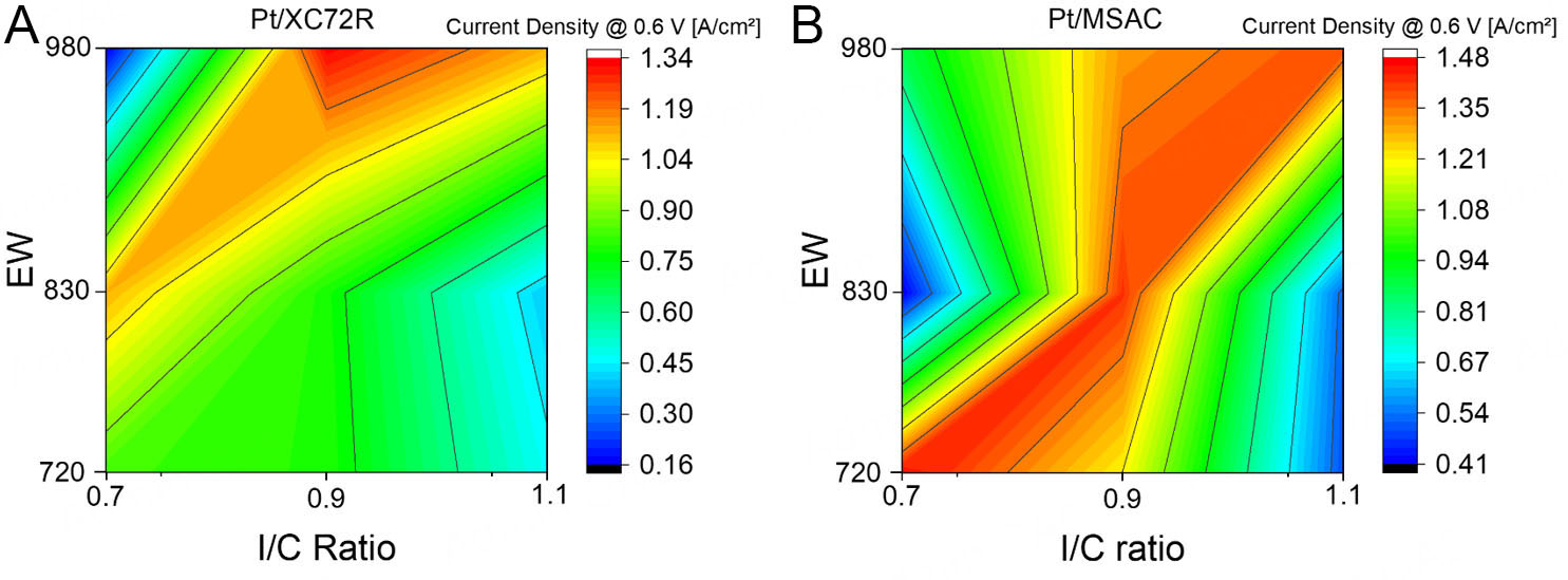
Figure 3. Current density map as a function of EW and I/C ratio: (A) for Pt/XC72R, (B) for Pt/MSAC.
• The x-axis represents the I/C ratio.
• The y-axis represents the ionomer EW.
• The color scale represents the resulting current density.
By incorporating catalysts with different surface properties, the current density map visualizes how performance varies with I/C ratio and ionomer EW, making material-dependent trends clearly visible. This map serves as a practical tool to streamline CL development by enabling targeted adjustments based on catalyst characteristics, reducing experimental workload and cost.
The core idea: a new catalyst's key properties (e.g., conductivity, isoelectric point, surface groups) are first assessed and used, as outlined in our previous study[31], to classify it as more similar to Pt/XC72R or Pt/MSAC. The corresponding map can then predict performance trends, guiding EW and I/C ratio selection.
Although based on a limited dataset (three I/C and EW values), the map captures clear patterns. Further refinement with expanded datasets and broader testing conditions could enhance its predictive power. Nonetheless, it already offers valuable early-stage guidance for MEA optimization and encourages broader adoption and data contributions from the community.
I/C ratio gradient
To embody these principles in practice, we selected Pt/XC72R with EW980 and I/C 0.9 as the reference system for our subsequent CL grading studies. This ensures that any observed enhancement can be robustly attributed to the grading architecture, rather than being distorted by an unoptimized baseline. Here, we investigated the effect of I/C ratio gradient at a constant ionomer EW of 980 on the PEMFC performance. The gradient configuration was designed with a high I/C ratio of 1.1 near the PEM, an intermediate I/C of 0.9 in the middle, and a low I/C of 0.7 GDL. The results are shown in Figure 4.
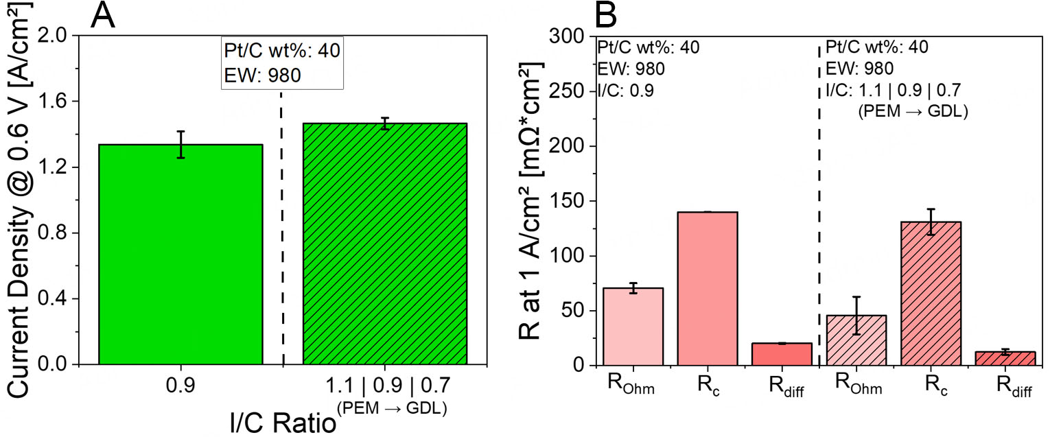
Figure 4. (A) Current densities at 0.6 V for Pt/XC72R CLs with I/C ratio gradient at constant EW980 at Pol 1, (B) EIS results for Pt/XC72R CLs featuring I/C ratio gradient at constant EW980 at Pol 1.
Figure 4A presents the current density results at 0.6 V for the I/C gradient configuration compared to the non-graded reference (at I/C 0.9 and EW980) under Pol 1 conditions. Under Pol 1 conditions, an increase in current density is observed, from approximately 1.33 to 1.46 A/cm2.
To better understand these observations, the corresponding EIS data measured at 1 A/cm2, depicted in Figure 4B, are analyzed. Under Pol 1 conditions (high humidity and high stoichiometry), the application of an I/C gradient leads to a clear enhancement in current density. This improvement is supported by EIS data, which show a notable decrease in Rohm. This reduction is attributed to improved proton conductivity near the membrane interface, resulting from the high I/C ratio in the proximal CL[17,20]. The higher ionomer content near the PEM promotes the formation of a continuous and well-hydrated proton-conducting network, thereby reducing the overall ionic resistance and facilitating efficient charge transport. In addition, Rc and Rdiff decrease which may be attributed to an enhanced three-phase boundary due to high I/C near the PEM, and improved mass transport due to lower I/C near the GDL[20,26].
Ionomer EW gradient
In the next step, we introduced an EW gradient across the CL while keeping the I/C ratio constant at 0.9. The configuration applied was EW720 near the PEM, EW 830 in the middle, and EW 980 near the GDL. This setup was chosen to investigate if a through-plane EW gradient, which theoretically balances proton conductivity and gas permeability, could enhance the PEMFC performance. The results are shown in Figure 5.
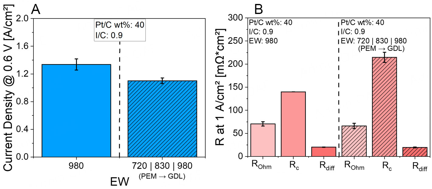
Figure 5. (A) Current densities at 0.6 V for Pt/XC72R CLs with an EW gradient at constant I/C 0.9 at Pol 1, (B) EIS data for the EW gradient at constant I/C 0.9 for Pt/XC72R CLs at Pol 1.
In the EW gradient study, the CLs were engineered to vary the EW through-plane: EW 720 near the PEM, EW 830 in the middle, and EW 980 near the GDL, while maintaining a constant I/C ratio of 0.9 across the entire CL. The goal of this configuration was to optimize ionic conductivity near the membrane while preserving porosity and mass transport pathways toward the GDL.
Figure 5A shows that the current density decreased under Pol 1 conditions compared to the ungraded reference CL. EIS data, presented in Figure 5B, indicate that under Pol 1 conditions, the dominant limiting factor is Rc, which increased significantly compared to the ungraded reference. This can likely be attributed to the swelling behavior of the membrane, particularly in the sub-layer adjacent to the PEM where EW720 was used. The excessive swelling may have hindered access to the Pt nanoparticles, thereby impeding the ORR.
A slight improvement in Rohm was observed, possibly due to the presence of EW720 near the membrane interface. The lower EW in this region may have enhanced the interfacial contact with the membrane, improving proton conductivity. Meanwhile, Rdiff remained relatively unchanged. This could be a result of the gradient configuration: toward the GDL, the EW increases, reducing the ionomer swelling. The use of EW980 near the GDL, known for its limited swelling behavior, appears beneficial, maintaining sufficient porosity and preventing deterioration of mass transport resistance.
Simultaneous I/C ratio and ionomer EW gradient
In the initial simultaneous EW and I/C gradient configuration, the following structure was applied: near the PEM, an I/C ratio of 1.1 with EW720; in the middle layer, an I/C of 0.9 with EW830; and near the GDL, an I/C of 0.7 with EW980. However, as shown in the Supplementary Figures 33 and 34, this configuration led to a decrease in current density compared to the ungraded reference layer.
To address this, a revised gradient structure was designed based on the best-performing combinations identified in the pre-optimization study. Specifically, near the PEM, a low I/C ratio of 0.7 was combined with a low EW of 720; in the middle layer, the same I/C of 0.7 was used with an intermediate EW of 830; and near the GDL, a higher I/C ratio of 0.9 was paired with a high EW of 980. This configuration aimed to simultaneously optimize ionic conductivity, catalyst utilization, and gas-phase mass transport across the CL thickness. The performance results for this optimized structure are presented in Figure 6.
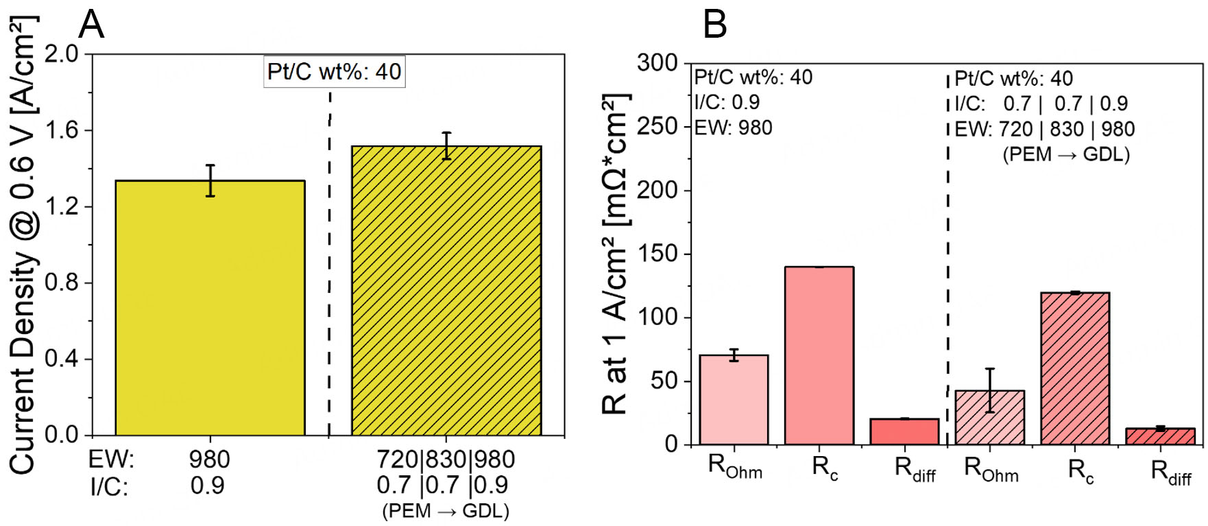
Figure 6. (A) Current densities at 0.6 V for Pt/XC72R CLs with simultaneous I/C and EW gradient at Pol 1, (B) EIS data corresponding to the simultaneous I/C and EW gradient in Pt/XC72R CLs at Pol 1.
Under Pol 1 conditions, which represent a humidified environment, the application of a simultaneous I/C and EW gradient, with EW720 at I/C 0.7 near the PEM, EW830 at I/C 0.7 in the mid-layer, and EW980 at
Furthermore, Rc is significantly reduced, indicating enhanced charge transfer kinetics. This can be explained by the well-hydrated environment and optimized ionomer coverage enabled by the gradient. The structure ensures that the ionomer is properly distributed along the Pt surface, especially near the PEM, where ORR activity is most critical. The EW and I/C gradients support a more favorable ionomer morphology with continuous triple-phase boundaries, thereby promoting effective access of reactants to active sites and improving electron and proton transport to these sites. Rdiff also decreases under Pol 1, which is attributed to the tailored porosity and gas transport pathways resulting from the EW gradient. Near the GDL, the higher EW980 at slightly higher I/C ensures sufficient porosity and minimizes excessive swelling, facilitating effective oxygen diffusion and water removal. The entire CL architecture balances water uptake, mechanical integrity, and porosity, leading to enhanced mass transport. The synergistic effect of the I/C and EW gradients optimizes ionomer distribution and connectivity, yielding a well-performing and structurally coherent CL under humidified conditions.
Pt/C loading gradient
Before discussing the Pt/C loading gradient configuration, it is important to first establish the baseline behavior observed for the non-graded CLs across different Pt loadings under Pol 1 conditions. The results are shown in Figure 7.
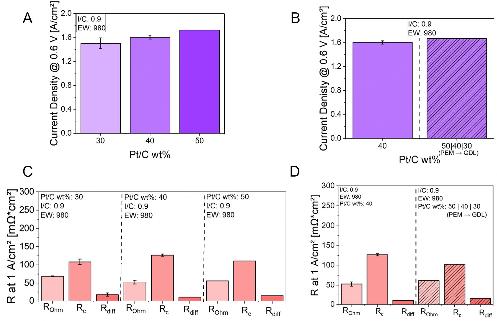
Figure 7. Current densities at 0.6 V for varying Pt/C loadings and Pt/C gradient: (A) Comparison of 30, 40, and 50 wt% Pt/C layers at Pol 1, (B) Current densities at 0.6 V for Pt/C loading gradient configuration at Pol 1, (C) EIS data for ungraded Pt/C CLs (30, 40, and
Under Pol 1 conditions, increasing the Pt/C loading from 30 to 50 wt% leads to a noticeable improvement in current density, rising from approximately 1.50 to 1.70 A/cm2 [see Figure 7A]. This performance gain may be primarily due to structural and compositional changes in the CL. In addition to an increase in active sites, as the Pt loading increases, while keeping the overall Pt loading per geometric area constant, the CL becomes thinner due to the reduced carbon content. This thinning shortens the transport paths for protons and electrons, thereby reducing internal resistances and enhancing catalyst utilization.
Analyzing the EIS data at 1 A/cm2, summarized in Figure 7C, provides further insights. When the Pt loading increases from 30 to 40 wt%, both Rohm and the mass Rdiff decrease. The drop in Rohm may be attributed to the thinner CL, which reduces the proton conduction path length and thus facilitates easier ion transport. Similarly, Rdiff decreases because the thinner layer reduces the diffusion distance for reactant gases, allowing for faster mass transport, despite a slight reduction in porosity. However, Rc increases in this range. This may result from the lower carbon content reducing the available surface area for ionomer dispersion, leading to less optimal formation of the three-phase boundary and thus reduced accessibility of protons to Pt sites.
As the Pt loading increases from 40 to 50 wt%, the CL becomes thinner and increasingly dominated by platinum. While carbon support is still present, the amount of free carbon surface area, available for ionomer interaction, decreases significantly due to the denser Pt coverage. This is supported by the Brunauer-Emmett-Teller (BET) surface area provided in Table 1, which suggests a reduction from
To address this trade-off, a Pt/C-graded CL structure was investigated. Here, 50 wt% Pt/C was placed near the PEM, 40 wt% in the mid-layer, and 30 wt% near the GDL. Figure 7B presents the current densities at
EIS data, shown in Figure 7D, reveal that under Pol 1 conditions, the dominant limiting factor is the charge transfer resistance Rc. It is likely that the high Pt loading of 50 wt% near the PEM promotes improved ORR kinetics, particularly due to the high proton density typically present in this region. This is reflected in the reduction of Rc compared to the ungraded reference layer.
Simultaneous I/C, ionomer EW and Pt/C loading gradient
For the final grading approach, combining I/C ratio, ionomer EW, and Pt/C loading content, the configuration was established with EW 720, I/C 0.7, and 50 wt% Pt near the PEM; EW 830, I/C 0.7, and
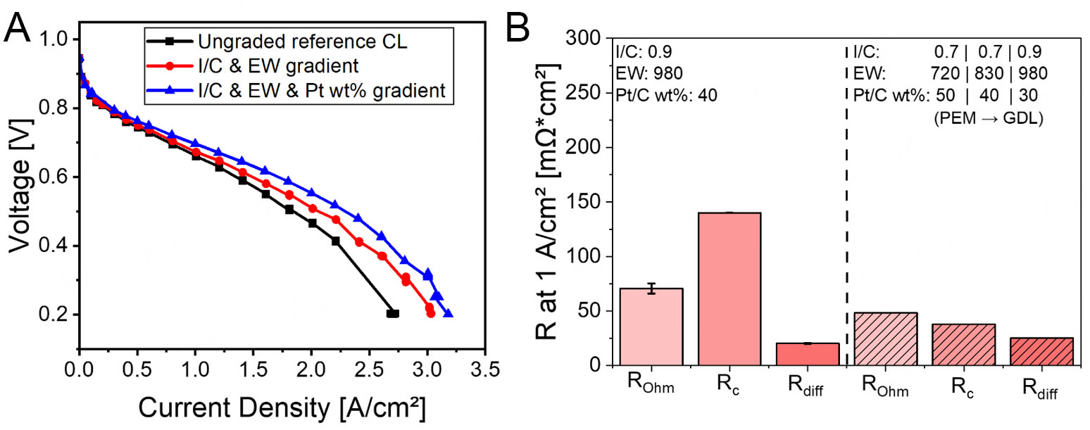
Figure 8. Polarization curves comparing: (A) Ungraded (optimized) layer, simultaneous I/C & EW gradient, and simultaneous I/C, EW, & Pt/C gradient at Pol 1, (B) EIS data for the CLs featuring simultaneous I/C, EW, and Pt/C gradient at Pol 1.
The combined gradient configuration led to an increase in current density compared to the ungraded reference CL [see Figure 8A]. EIS results under Pol 1 conditions, summarized in Figure 8B, show a decrease in all key resistances, particularly Rohm and Rc. The reduction in Rohm can be attributed to the use of a low EW ionomer (EW720) and a low I/C ratio (0.7) near the membrane interface. This enhances proton conduction by improving the contact between the CL and the PEM, and by reducing interfacial resistance. The drop in Rohm also suggests that the membrane-CL interface benefits from improved hydration and homogeneous ionomer distribution.
The large decrease in Rc is likely the result of introducing the Pt/C gradient. Placing 50 wt% Pt near the PEM increases the local Pt density per unit thickness, improving Pt utilization and ensuring closer contact between Pt and ionomer due to the reduced carbon fraction. Moreover, combining this with a low I/C ratio further enhances ionomer-Pt connectivity, reducing electronic and ionic barriers at the reaction sites. The smoother transitions in both EW and I/C across the CL prevent morphological mismatches and aggregation effects, which often contribute to higher Rc in less-optimized structures.
Rdiff remains similar to the ungraded reference. This suggests that gas-phase transport is not negatively affected by the gradient structure. The 30 wt% Pt region near the GDL, combined with high EW (980) and higher I/C (0.9), maintains sufficient porosity and hydrophobicity to support oxygen diffusion and water removal, balancing the higher-density regions near the PEM.
Overall, the fully graded CL demonstrated a ~32% increase in performance at Pol 1 and ~17% at Pol 2 [see Supplementary Figure 29], validating the efficacy of this design strategy. Beyond performance gains, this approach enables enhanced Pt utilization, reduced ionomer usage, and improved water management, especially under humid and high stoichiometry conditions. Specifically, the graded CL led to a Pt cost reduction from $7.2/kW to $5.5/kW (~23%) at Pol 1, and from $7.4/kW to $6.3/kW (~15%) at Pol 2. Ionomer consumption was similarly reduced, from 0.35 to 0.25 g/kW (~27%) at Pol 1, and from 0.36 to
From a manufacturing perspective, implementing graded CLs entails additional complexity due to the need for multiple sequential spray steps. This would require either multiple nozzles or a switchable ink supply system, leading to increased equipment costs and maintenance effort. While not quantified here, such requirements could moderately raise operational costs in large-scale production. However, based on preliminary cost estimates from lab-scale experiments, the additional expenses for implementing a multi-nozzle spray setup remain within a moderate range of a few thousand euros. More critical than equipment costs is the reliable formulation and handling of multiple catalyst inks. Ensuring consistent ink properties is essential for reproducible gradient layer formation and long-term scalability.
CONCLUSION
This study systematically investigated the impact of graded CL designs in PEMFCs, focusing on controlled variations in I/C ratio, ionomer EW, and Pt/C loading. A pre-optimization study was first conducted to identify the optimal parameter ranges for each variable. This step was essential to establish a clear performance baseline and to guide the design of gradient configurations. Based on the current density distribution map obtained in this study, the most promising through-plane cathode CL gradient designs resulting from combinations of I/C, EW, and Pt/C were identified and subsequently used to fabricate advanced CLs for PEMFC.
Single-parameter gradients, whether in EW, I/C, or Pt/C, resulted in modest performance changes and in some cases even led to higher ohmic, cathode charge transfer, and/or gas transport resistances. In contrast, simultaneous gradients across multiple parameters showed substantial improvements. The most effective CL design, combining gradients in EW, I/C ratio, and Pt/C loading, achieved the highest performance gains: current densities improved by approximately 32% under humid and high stoichiometry conditions, and by 17% under dry and low stoichiometry conditions, relative to the non-graded reference CL.
EIS confirmed that these enhancements were mainly driven by reduced cathode charge transfer and ohmic resistances. The combination of low-EW ionomers and low I/C near the membrane improved proton conduction even under low humidity, while higher I/C and high EW near the GDL preserved porosity and oxygen accessibility. Notably, the Pt/C gradient enabled more efficient catalyst utilization by concentrating higher Pt and optimized ionomer loadings where kinetics are most favorable, and reducing material use elsewhere.
In summary, this work demonstrates that well-designed, multi-parameter gradient CLs can overcome conventional trade-offs in performance and cost. The combined approach offers a viable pathway toward more efficient, durable, and economically viable PEMFCs. While all electrochemical analyses were primarily performed with Nafion HP membranes, additional validation experiments with FumaPEM FS-715 [See Supplementary Figure 35] confirmed the robustness of the observed effects across different membrane types. This suggests that the graded CL concept is not restricted to a specific membrane chemistry or structure.
While the present study focuses on electrochemical performance and transport phenomena in graded cathode CLs, future work will aim to systematically correlate these findings with structural and compositional features. Specifically, we are currently developing a robust scanning electron microscopy/energy-dispersive X-ray Spectroscopy (SEM/EDX)-based cross-sectional analysis protocol to visualize and quantify gradient profiles within the CL[34]. This methodology will enable a deeper understanding of how spatial variations in composition and structure influence performance, and support the refinement of fabrication strategies. The integration of electrochemical characterization with such high-resolution structural analysis will provide a comprehensive structure-property-performance framework for graded electrodes in PEMFCs. To illustrate the current progress, we have included a preliminary SEM-EDX cross-section (provided in Supplementary Figure 36) that demonstrates the direction of our current development work. These images represent early-stage methodological efforts, rather than fully validated results. A dedicated study is planned to correlate these structural insights with electrochemical performance in a statistically rigorous manner.
DECLARATIONS
Authors’ contributions
Conceptualization, investigation, methodology, resources, validation, visualization, writing - original draft preparation: Caidi, A.
Conceptualization, project administration, resources, supervision, validation, visualization, writing - review & editing: Lange, T.
Validation, visualization, writing - review & editing: Radev, I.
Conceptualization, funding acquisition, project administration, resources: Peinecke, V.
Investigation: Grimm, K.
Conceptualization, project administration, resources, supervision, validation, visualization, writing - review & editing: Özcan, F.
Conceptualization, funding acquisition, project administration, resources, supervision, validation, visualization, writing - review & editing: Segets, D.
Availability of data and materials
The data supporting the findings of this study are open available on Zenodo at https://zenodo.org/records/17054239 (DOI: 10.5281/zenodo.17054238).
Financial support and sponsorship
This research is funded by the German federal ministry of education and research as part of the project (No. 21430 N) “Entwicklung einer stofftransport- und porositätsoptimierten gradierten Katalysatorschicht mit hoher Platin-Ausnutzung für PEM-Brennstoffzellen durch Kombination von Laserablations- und Nassmahltechnologien” (TRAGRAKAT).
Policy of the Use of AI and AI-assisted Technologies in Scientific Writing
During the preparation of this work, the authors used ChatGPT-4 to enhance the readability and language of the manuscript. Following the use of this tool, the authors thoroughly reviewed and edited the content, assuming full responsibility for the content of the publication.
Conflicts of interest
Caidi, A.; Lange, T.; Radev, I.; Grimm, K.; and Peinecke, V. are affiliated with ZBT GmbH, while the other authors have declared that they have no conflicts of interest.
Ethical approval and consent to participate
Not applicable.
Consent for publication
Not applicable.
Copyright
© The Author(s) 2025.
Supplementary Materials
REFERENCES
1. Zhang, J. PEM fuel cell electrocatalysts and catalyst layers. London: Springer; 2008.
2. Chen, G.; Wang, C.; Lei, Y.; et al. Gradient design of Pt/C ratio and Nafion content in cathode catalyst layer of PEMFCs. Int. J. Hydrogen. Energy. 2017, 42, 29960-5.
3. Kulikovsky, A. A model for optimal catalyst layer in a fuel cell. Electrochim. Acta. 2012, 79, 31-6.
4. Ayoub, M.; Böhm, T.; Bierling, M.; Thiele, S.; Brodt, M. Review - graded catalyst layers in hydrogen fuel cells - a pathway to application-tailored cells. J. Electrochem. Soc. 2024, 171, 094503.
5. Garsany, Y.; Atkinson, R. W.; Gould, B. D.; et al. Dual-layer catalyst layers for increased proton exchange membrane fuel cell performance. J. Power. Sources. 2021, 514, 230574.
6. Baricci, A.; Bonanomi, M.; Yu, H.; Guetaz, L.; Maric, R.; Casalegno, A. Modelling analysis of low platinum polymer fuel cell degradation under voltage cycling: gradient catalyst layers with improved durability. J. Power. Sources. 2018, 405, 89-100.
7. Yu, H.; Baricci, A.; Casalegno, A.; Guetaz, L.; Bonville, L.; Maric, R. Strategies to mitigate Pt dissolution in low Pt loading proton exchange membrane fuel cell: II. A gradient Pt loading design. Electrochim. Acta. 2017, 247, 1169-79.
8. Kim, G.; Eom, K.; Kim, M.; et al. Design of an advanced membrane electrode assembly employing a double-layered cathode for a PEM fuel cell. ACS. Appl. Mater. Interfaces. 2015, 7, 27581-5.
9. Fofana, D.; Natarajan, S. K.; Hamelin, J.; Benard, P. Low platinum, high limiting current density of the PEMFC (proton exchange membrane fuel cell) based on multilayer cathode catalyst approach. Energy 2014, 64, 398-403.
10. Roshandel, R.; Ahmadi, F. Effects of catalyst loading gradient in catalyst layers on performance of polymer electrolyte membrane fuel cells. Renew. Energy. 2013, 50, 921-31.
11. Matsuda, H.; Fushinobu, K.; Ohma, A.; Okazaki, K. Structural effect of cathode catalyst layer on the performance of PEFC. J. Ther. Sci. Technol. 2011, 6, 154-63.
12. Jain, P.; Biegler, L. T.; Jhon, M. S. Optimization of polymer electrolyte fuel cell cathodes. Electrochem. Solid. State. Lett. 2008, 11, B193.
13. Taylor, A. D.; Kim, E. Y.; Humes, V. P.; Kizuka, J.; Thompson, L. T. Inkjet printing of carbon supported platinum 3-D catalyst layers for use in fuel cells. J. Power. Sources. 2007, 171, 101-6.
14. Huang, X.; He, Y.; Sun, Y.; Sun, L.; Wang, T.; Zhang, X. Gradient ionomer designed cathode catalyst layer for proton exchange membrane fuel cells with enhanced performance. J. Power. Sources. 2024, 603, 234488.
15. Zhang, X.; Shi, P. Dual-bonded catalyst layer structure cathode for PEMFC. Electrochem. Commun. 2006, 8, 1229-34.
16. Xie, Z.; Navessin, T.; Shi, K.; et al. Functionally graded cathode catalyst layers for polymer electrolyte fuel cells: II. Experimental study of the effect of nafion distribution. J. Electrochem. Soc. 2005, 152, A1171.
17. Yoon, Y.; Yang, T.; Park, G.; Lee, W.; Kim, C. A multi-layer structured cathode for the PEMFC. J. Power. Sources. 2003, 118, 189-92.
18. Wang, Q.; Eikerling, M.; Song, D.; et al. Functionally graded cathode catalyst layers for polymer electrolyte fuel cells: I. Theoretical modeling. J. Electrochem. Soc. 2004, 151, A950.
19. Nguyen, H.; Sultanova, D.; Heizmann, P. A.; Vierrath, S.; Breitwieser, M. Improving the efficiency of fully hydrocarbon-based proton-exchange membrane fuel cells by ionomer content gradients in cathode catalyst layers. Mater. Adv. 2022, 3, 8460-8.
20. Shahgaldi, S.; Ozden, A.; Li, X.; Hamdullahpur, F. Cathode catalyst layer design with gradients of ionomer distribution for proton exchange membrane fuel cells. Energy. Convers. Manag. 2018, 171, 1476-86.
21. Jung, D. W.; Kim, J. H.; Kim, S. H.; Kim, J. B.; Oh, E. S. Performance enhancement of polymer electrolyte membrane fuel cells by dual-layered membrane electrode assembly structures with carbon nanotubes. J. Nanosci. Nanotechnol. 2013, 13, 3650-4.
22. Su, H.; Liao, S.; Wu, Y. Significant improvement in cathode performance for proton exchange membrane fuel cell by a novel double catalyst layer design. J. Power. Sources. 2010, 195, 3477-80.
23. Xuan, Z.; Fang, W.; Zhao, G.; Tao, W. Optimal gradient designs of catalyst layers for boosting performance: a data-driven-assisted model. Appl. Energy. 2025, 377, 124756.
24. Xing, L.; Shi, W.; Das, P. K.; Scott, K. Inhomogeneous distribution of platinum and ionomer in the porous cathode to maximize the performance of a PEM fuel cell. AIChE. J. 2017, 63, 4895-910.
25. Srinivasarao, M.; Bhattacharyya, D.; Rengaswamy, R. Optimization studies of a polymer electrolyte membrane fuel cell with multiple catalyst layers. J. Power. Sources. 2012, 206, 197-203.
26. Srinivasarao, M.; Bhattacharyya, D.; Rengaswamy, R.; Narasimhan, S. Performance analysis of a PEM fuel cell cathode with multiple catalyst layers. Int. J. Hydrogen. Energy. 2010, 35, 6356-65.
27. Song, D.; Wang, Q.; Liu, Z.; et al. A method for optimizing distributions of Nafion and Pt in cathode catalyst layers of PEM fuel cells. Electrochim. Acta. 2005, 50, 3347-58.
28. Lei, H.; Xing, L.; Jiang, H.; et al. Designing graded fuel cell electrodes for proton exchange membrane (PEM) fuel cells with recurrent neural network (RNN) approaches. Chem. Eng. Sci. 2023, 267, 118350.
29. Zhao, G.; Fang, W.; Xuan, Z.; Tao, W. Optimization of gradient catalyst layers in PEMFCs based on neural network models. Energies 2025, 18, 2570.
30. Liu, Z.; Yang, W.; Zhang, J.; Lin, Y.; Zhang, J.; Qu, Z. Gradient catalyst layer design for low-Pt-loading PEM fuel cell based on artificial neural network and multi-objective optimization. Int. J. Hydrogen. Energy. 2025, 141, 650-64.
31. Caidi, A.; Lange, T.; Radev, I.; Peinecke, V.; Özcan, F.; Segets, D. Impact of sonication treatment on physicochemical properties of carbon blacks and Pt/C catalysts in proton exchange membrane fuel cells. Particle. Particle. Syst. Charact. 2025, e00057.
32. Lin, R.; Wang, H.; Zhu, Y. Optimizing the structural design of cathode catalyst layer for PEM fuel cells for improving mass-specific power density. Energy 2021, 221, 119909.
33. Kim, K.; Kim, H.; Lee, K.; et al. Effect of Nafion® gradient in dual catalyst layer on proton exchange membrane fuel cell performance. Int. J. Hydrogen. Energy. 2008, 33, 2783-9.
Cite This Article
How to Cite
Download Citation
Export Citation File:
Type of Import
Tips on Downloading Citation
Citation Manager File Format
Type of Import
Direct Import: When the Direct Import option is selected (the default state), a dialogue box will give you the option to Save or Open the downloaded citation data. Choosing Open will either launch your citation manager or give you a choice of applications with which to use the metadata. The Save option saves the file locally for later use.
Indirect Import: When the Indirect Import option is selected, the metadata is displayed and may be copied and pasted as needed.
About This Article
Copyright

Data & Comments
Data
0


Comments
Comments must be written in English. Spam, offensive content, impersonation, and private information will not be permitted. If any comment is reported and identified as inappropriate content by OAE staff, the comment will be removed without notice. If you have any queries or need any help, please contact us at [email protected].