


Robust nickel single-atom catalyst for high-efficiency and stable vanadium-cerium redox flow batteries
 0
0 Abstract
Vanadium-cerium redox flow batteries (V-Ce RFBs) have emerged as a promising alternative to all-vanadium systems due to the lower cost and high standard redox potential of Ce3+/Ce4+. However, their practical application is hindered by the sluggish kinetics of the Ce3+/Ce4+ redox reaction and the severe corrosion of conventional graphite felt electrodes. To address these challenges, we constructed a single atomic nickel catalyst (Ni1/NC) with a four-nitrogen coordination structure (Ni1–N4 moiety) on nitrogen-doped carbon support. The Ni1/NC catalyst with high Ni loading possesses abundant accessible active sites and unique structure properties for catalysis. When applied as a positive electrode, the Ni1/NC catalyst exhibited significantly enhanced electrocatalytic activity and stability for Ce3+/Ce4+ redox. The assembled V-Ce RFBs achieves a high energy efficiency of 69.1% at 200 mA cm-2 and a superior peak power density, markedly outperforming cells with baseline electrodes. Density functional theory calculations reveal that the Ni1–N4 sites facilitate charge transfer and enhance activation of reactant species (Ce4+), providing atomic-level insight into the catalytic mechanism. This work demonstrates the effectiveness of single-atom catalysts in enhancing the performance of V-Ce RFBs and sheds light on designing advanced electrocatalysts.
Keywords
INTRODUCTION
Amid the global transition toward low-carbon energy systems, the rapid expansion of solar and wind power has intensified the demand for advanced energy storage technologies capable of mitigating the intermittency and volatility inherent to these renewable sources[1,2]. Redox flow batteries (RFBs), which store and release electrical energy via reversible redox reactions between the catholyte and anolyte, are widely regarded as one of the most promising technologies for large-scale energy storage applications due to their inherent safety and long cycle life[3,4]. Within the landscape of RFBs technologies, all-vanadium systems (VRFBs) have emerged as a focal point of extensive research and development[5-7]. However, the biological toxicity and high cost of vanadium compounds (e.g., V2O5 at ≈ $10,200 per ton) remain major obstacles, motivating the exploration for alternative redox couples[8,9].
Recently, the Ce3+/Ce4+ redox couple has been demonstrated as a compelling candidate, owing to the significantly lower cost of cerium (the price of CeO2 is around one-tenth that of V2O5) and the high standard redox potential of Ce3+/Ce4+ [1.72 V vs. standard hydrogen electrode (SHE)][10]. However, this strong oxidizing capability also accelerates electrode corrosion and degradation in acidic media, undermining system stability[11]. Consequently, the practical implementation of vanadium-cerium (V-Ce) RFBs is largely constrained by the performance of the positive electrode[12,13]. Owing to the strong acid electrolyte environment, electrodes based on metals and metal oxides are prone to dissolution. However, graphite felt (GF), the most commonly used electrode material in RFBs, offers limited intrinsic catalytic activity and insufficient stability during extended cycling[14,15]. This limitation becomes more pronounced at elevated operating voltages, which accelerate electrode corrosion and lead to the formation of degradation products such as CO and CO2[16]. Additionally, the scarcity of available active sites on GF results in sluggish Ce3+/Ce4+ redox reaction kinetics, thereby constraining the energy efficiency (EE), discharge capacity, and power density of the system[17]. Collectively, these issues significantly impair the overall charge-discharge performance of V-Ce RFBs.
Single-atom catalysts (SACs) have recently emerged as a highly promising class of electrocatalysts due to their maximum atom utilization, well-defined active sites, and unique electronic structures[18,19]. Various SACs can be deposited and stabilized on various supports (e.g., carbon, oxide, metal, and zeolite), providing broad structural flexibility and catalytic feasibilities[20,21]. Their abundant accessible active sites and unique coordination environments make SACs particularly attractive for enhancing electrocatalytic activity and stability in RFB systems[22]. For VRFBs, SACs anchored on heteroatom-doped carbon substrates have demonstrated excellent resistance to strongly acidic electrolytes[23]. For example, Xing et al. developed Bi SACs supported on GF that enabled a remarkable peak power density of 990 mW cm-2 at 240 mA cm-2 for VRFBs[24]. However, existing research has focused almost exclusively on VRFBs, leaving their catalytic behavior and mechanistic roles in V-Ce RFBs largely unexplored[25].
Herein, we constructed a nickel-based single atomic catalyst (Ni1/NC) with a four-nitrogen coordination structure (Ni1–N4 moiety) on nitrogen-doped carbon (NC) support. The atomic dispersion and coordination environment of Ni SACs were confirmed by aberration correction high-angle annular dark-field scanning transmission electron microscopy (AC HAADF-STEM), X-ray absorption fine structure (XAFS), and density functional theory (DFT) calculation. Compared to pristine GF and NC, Ni1/NC exhibited significantly enhanced electrocatalytic activity toward the Ce3+/Ce4+ redox reaction. When employed as the positive electrode in a V-Ce RFB, the Ni1/NC-modified electrode delivers a high EE of 65.1% at 200 mA cm-2 over 100 cycles and a peak power density of 551.4 mW cm-2, outperforming the NC-modified electrode (42.8% and 466.4 mW cm-2) and pristine GF (41.5% and 443.4 mW cm-2). DFT analysis further reveals that the Ni1–N4 moiety serves as the primary active center, enhancing charge transfer and reducing the reaction energy barrier at the electrode-electrolyte interface. This work demonstrates the effectiveness of SACs in V-Ce RFBs and provides valuable insights into the rational design of next-generation electrocatalysts for high-performance RFBs.
EXPERIMENTAL
Materials
All chemicals were purchased from commercial suppliers and used without further purification: VOSO4 (Aladdin, shanghai, China); Ce2(CO3)3 (Aladdin, shanghai, China); H2SO4 (XILONG SCIENCE, Guangdong, China); CH4O3S (Sigma-Aldrich, shanghai, China); NiCl2·6H2O (Aladdin, shanghai, China); Zn(NO3)2·6H2O (Aladdin, shanghai, China); C5H8N2 (Aladdin, shanghai, China); KCl (Aladdin, shanghai, China); Hydrochloric acid (Aladdin, shanghai, China); Ethanol (Aladdin, shanghai, China); Nafion D520 Dispersion (Chemours, shanghai, China); and C3H8O (Aladdin, shanghai, China).
Synthesis of NC, Ni1/NC and NiNP/NC
NC support was firstly synthesized by updating the method in literature[26]. Typically, 25.5 g Zn(NO3)2·6H2O and 58.3 g 2-methylimidazole were dissolved separately in 2.0 L of deionized water. Then, the two solutions were mixed rapidly and stirred vigorously for 2 h. The resulting white suspension was aged under undisturbed conditions for 12 h to form a white precipitate. Next, the white precipitate was collected by filtration, and subsequently washed with water and ethanol to yield two-dimensional (2D) ZIF-8. Then, 10 g 2D ZIF-8 and 200 g KCl were dispersed in 800 mL deionized water and then dried by rotary evaporation to obtain a composite powder. The powder was pyrolyzed at 700 °C for 5 h under a continuous Ar flow with a controlled ramp rate of 2 °C∙min-1. The resultant solid was subjected to sequential washing cycles with 2 M HCl, deionized water, and ethanol, followed by an overnight dehydration process at 80 °C.
Then 500 mg of NC was dispersed in 50 mL of ethanol and sonicated for 30 min. Subsequently, 50 mL of ethanol containing 250 mg NiCl2·6H2O was added, and the mixture was magnetically stirred for an additional 2 h. After drying with a rotary evaporator, the mixture was transferred into a tube furnace and pyrolyzed at 300 °C for 5 h with a heating rate of
For comparison, Ni nanoparticles loading on NC support (denoted as NiNP/NC) was synthesized using an identical procedure for Ni1/NC but omitting the initial pyrolysis step at 300 °C.
Material characterization
Transmission electron microscopy (TEM) images, HAADF-STEM image, and energy-dispersive X-ray spectroscopy (EDS) were performed on JEM-2100F (JEOL, Tokyo, Japan) at 200 kV. AC HAADF-STEM images were performed on a JEOL JEM-ARM300F (JEOL, Tokyo, Japan) at 300 kV. X-ray diffraction (XRD) patterns were recorded on a D8 Advance (Bruker, Germany) diffractometer with Cu Kα radiation
Electrochemical measurement of Ni1/NC, NiNP/NC, and NC catalysts
Ni1/NC, NiNP/NC, and NC catalysts were deposited onto pristine GF substrates to fabricate the working electrodes. Specifically, 10 mg of catalyst was dispersed in a mixture containing 600 μL of isopropanol, 150 μL of ultrapure water, and 50 μL of Nafion solution via ultrasonication. The resulting homogeneous ink was uniformly sprayed onto both sides of the GF using an airbrush, followed by drying. For comparative analysis, the prepared electrodes are denoted as Ni1/NC, NiNP/NC, and NC electrodes.
The electrochemical tests were performed in a typical three-electrode cell. The working electrode is a 2 cm2 GF, NC, and Ni1/NC electrode, the counter electrode is titanium plate, and the reference is a saturated calomel electrode (SCE). The electrolyte consisted of 15 mL solution containing 0.05 M Ce2(CO3)3, 3 M methanesulfonic acid (MSA), and 0.5 M H2SO4. Potentiostatic electrochemical impedance spectroscopy (PEIS) were collected with a CS3104 electrochemical workstation at an applied amplitude of 10 mV within the frequency range from 0.01 Hz to 1.0 M Hz.
RFB performance evaluation
In a typical RFB configuration, a Nafion N117 cation exchange membrane and electrodes (4 cm2) were compressed and sealed using two titanium end plates, with a rubber gasket serving as the sealing ring. During operation, the positive electrolyte consisted of 20 mL solution containing 0.2 mol·L-1 Ce2(CO3)3,
Computational details
DFT calculations were performed using the Vienna Ab initio Simulation Package (VASP). The exchange-correlation interactions were treated within the generalized gradient approximation (GGA) using the Perdew-Burke-Ernzerhof (PBE) functional[28,29]. The electron-ion interactions were modeled with the projector augmented wave (PAW) method, with a plane-wave basis set defined by a kinetic energy cutoff of 450 eV. For electronic structure iterations, a convergence criterion of 10-4 eV was established to ensure self-consistency. Additionally, the partial occupancies of the Kohn-Sham orbitals were refined using a Gaussian smearing width of 0.05 eV[30]. Structural relaxations were performed until the maximum force on any atom was less than 0.05 eV·Å-1. The formation energy (Ef) was evaluated according to the following expression[31]:
Where Etot denotes the total energy of the configured system; nC, nNi, and nN represent the number of carbon, nickel, and nitrogen atoms, respectively; and μC, μNi, and μN refer to the chemical potentials of carbon, nickel, and nitrogen, referenced to graphite, hexagonal close-packed (hcp) Ni metal, and the N2 molecule, respectively. A negative Ef value indicates thermodynamic stability relative to the constituent elements. Additionally, the charge density difference was computed as[32]:
Here, ρad/sub corresponds to the total charge density of the optimized adsorbate-substrate complex, while ρad and ρsub represent the charge densities of the isolated adsorbate and substrate, respectively, each frozen in the geometry adopted in the fully relaxed composite system.
RESULTS AND DISCUSSION
Characterization of Ni1/NC
Ni1/NC SAC was prepared via an impregnation-pyrolysis strategy, as illustrated in Figure 1A. The morphology and atomic-level structure features of NC and Ni1/NC were resolved. TEM images [Supplementary Figure 1] reveal that NC exhibits a 2D ultrathin nanosheet structure, consistent with the 2D structure of ZIF-8 precursor [Supplementary Figure 2]. The absence of graphite lattice fringes in the high-resolution TEM image [Supplementary Figure 1C] suggested the amorphous carbon structure of NC, which was further confirmed by Raman spectroscopy [Supplementary Figure 3]. N2 sorption plots show that NC exhibits a typical microporous structure with average pore size of 4.2 nm and a large Brunauer-Emmett-Teller (BET) surface area of 1,827 m2 g-1 [Supplementary Figure 4]. For Ni1/NC, both TEM images [Figure 1B, Supplementary Figures 5 and 6] and low-magnification HAADF-STEM image [Figure 1C] reveal a similar morphology to that of NC, indicating the atomic dispersion of Ni species. The absence of Ni nanoparticles was also verified by XRD [Supplementary Figure 7]. AC HAADF-STEM images of Ni1/NC [Figure 1D and E] reveal numerous isolated bright dots, ascribed to individual Ni atoms due to the atomic number (Z) contrast between Ni and lighter elements in the support[33]. Besides, EDS mapping revealed a uniform distribution of Ni, C, and N across the substrate, with a Ni and N mass fraction of 9.2% and 15.2%, respectively [Supplementary Figure 8 and Supplementary Table 1]. The high N content provides abundant sites for the anchoring of Ni single atoms.
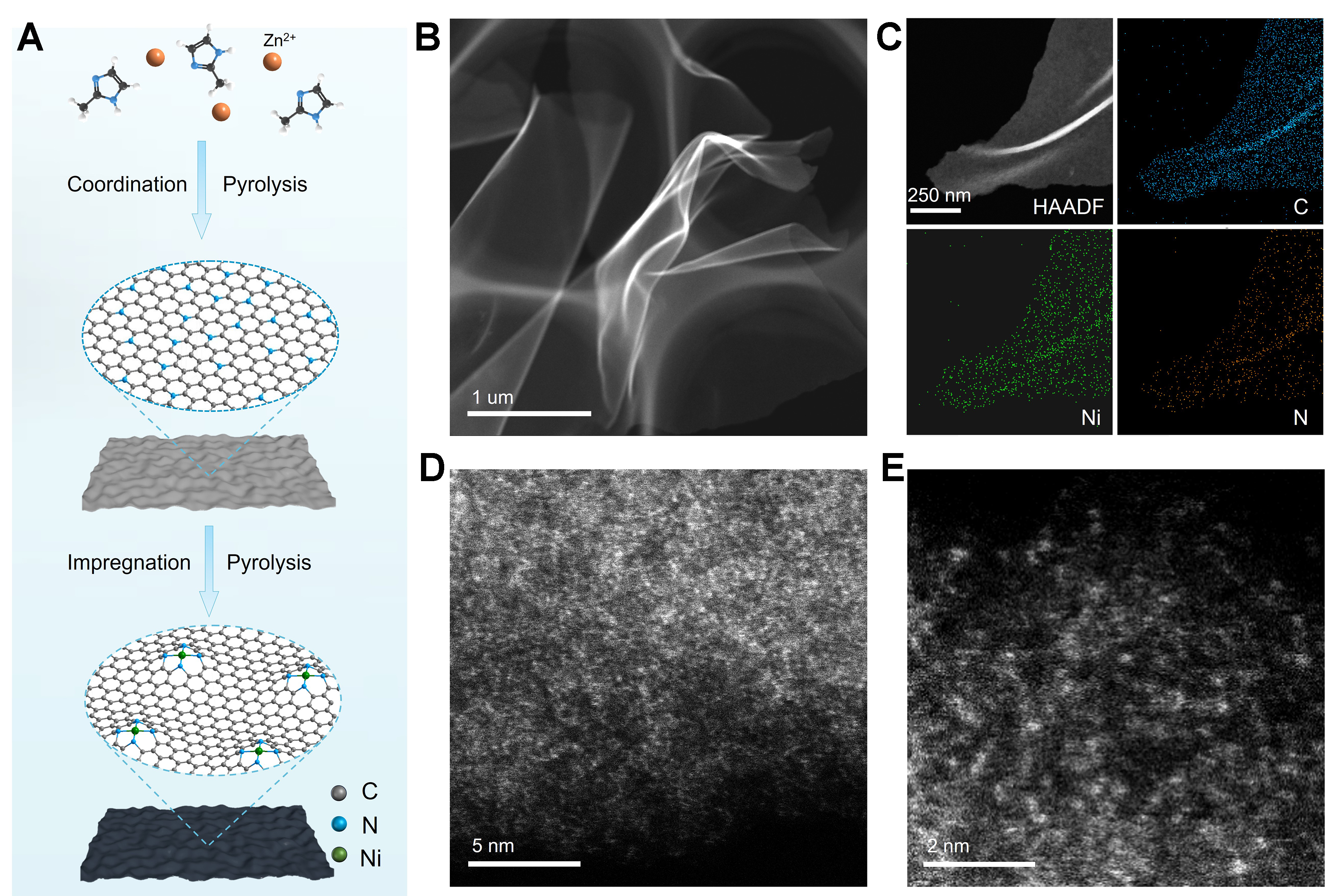
Figure 1. Synthesis process and structure characterizations of Ni1/NC. (A) Schematic illustration of the synthesis process for Ni1/NC; (B) Low-magnification HAADF-STEM image; (C) EDS element mapping, and (D and E) AC HAADF-STEM images of Ni1/NC. NC: Nitrogen-doped carbon; HAADF-STEM: high-angle annular dark-field scanning transmission electron microscopy; EDS: energy-dispersive X-ray spectroscopy; AC: aberration correction.
XPS was then performed to study the valence states of Ni1/NC [Figure 2A and B, Supplementary Table 1]. The Ni 2p spectrum of Ni1/NC [Figure 2A] displays characteristic peaks at binding energies of 855.6 eV for Ni 2p3/2 and 872.6 eV for Ni 2p1/2, along with corresponding satellite peaks, suggesting the oxidation state of Ni (Niδ+) resulting from the Ni-support interactions[34]. In the N 1s spectrum of Ni1/NC [Figure 2B], besides pyridinic N (397.8 eV), pyrrolic N (399.6 eV), graphitic N (400.8 eV), and oxidized N (402.5 eV), a peak located at 398.5 eV corresponding to Ni–N bonding is also observed, indicating the existence of Ni–N coordination structure in Ni1/NC.
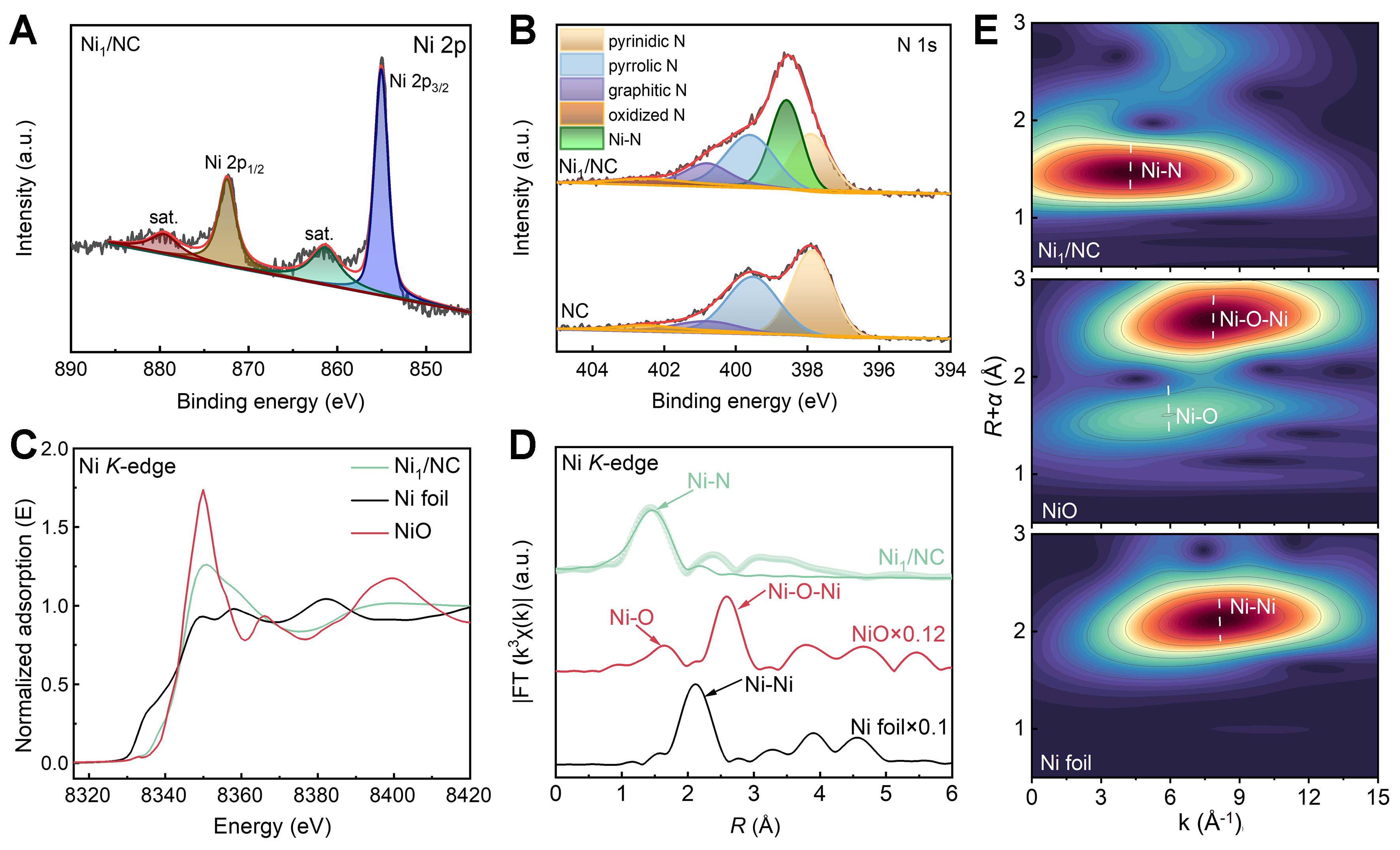
Figure 2. Chemical states and coordination environment of Ni1/NC. (A) Ni 2p and (B) N 1s XPS spectra of samples; (C) Ni K-edge XANES, (D) FT-EXAFS, and (E) WT for the EXAFS signal of Ni1/NC and references. NC: Nitrogen-doped carbon; XPS: X-ray photoelectron spectroscopy; XANES: X-ray absorption near edge structure; FT-EXAFS: Fourier transformed-extended X-ray absorption fine structure; WT: wavelet transform.
The chemical states and coordination environment of Ni were further investigated by using synchrotron radiation based XAFS. As illustrated in the normalized Ni K-edge X-ray absorption near edge structure (XANES) spectra [Figure 2C], the absorption threshold of Ni1/NC is positioned between those of the Ni foil and NiO references, indicating that the Ni species in Ni1/NC possess an intermediate oxidation state between 0 and +2. The Ni K-edge XANES spectra [Figure 2C] reveal the position of the rising edge of Ni1/NC is between that of Ni foil and NiO, indicating that the oxidation state of Ni in Ni1/NC is between Ni0 and Ni2+. The unique electronic structure of Ni arises from coordination-induced charge transfer from Ni to N/C atoms. The Fourier transformed (FT)-EXAFS spectrum [Figure 2D] only displays a single prominent peak (~1.5 Å), which is attributed to the Ni–N scattering, suggesting the atomically dispersed Ni species in Ni1/NC[35,36]. The k space of k3-weighted FT-EXAFS of Ni1/NC [Supplementary Figure 9] reveals a unique profile that lacks the characteristic oscillations of Ni foil and NiO, further confirming the absence of nanoparticles. Wavelet transform (WT) analysis [Figure 2E] of Ni K-edge EXAFS oscillations only presents one maximum intensity (at ~4.5 Å-1) which is assigned to the Ni–N coordination, further supporting the isolated nature of Ni atoms[37]. Quantitative EXAFS curve fitting [Figure 2D and Supplementary Table 2] confirmed that the average Ni–N coordination number is estimated to be 3.8 with the average bond distance of 1.95 Å. Therefore, based on the EXAFS and XPS spectra, the local coordination structure of Ni in Ni1/NC can be identified as Ni1–N4 (as displayed in the bottom of Figure 1A), where a single Ni atom is coordinated by four N atoms embedded within the carbon matrix.
Electrochemical performance for catalytic Ce3+/Ce4+ redox
Working electrodes were fabricated by depositing Ni1/NC, or NC catalysts onto pristine GF substrates. The resulting electrodes were denoted as Ni1/NC, NC, and GF (pristine graphite felt) electrodes for comparative purposes. The electrocatalytic activity and reaction kinetics of these electrodes toward the Ce4+/Ce3+ redox couple were evaluated in a standard three-electrode system. As shown in Figure 3A-C, well-defined oxidation and reduction peaks are observed in the cyclic voltammetry (CV) curves for all electrodes, suggesting appreciable reversibility of the Ce3+/Ce4+ redox reaction. A direct comparison of the CV curves acquired at 3 mV s-1 [Figure 3D] reveals that the NC and GF electrodes exhibit relatively low peak current densities and large peak potential separation (ΔEp), indicating inferior electrocatalytic activity. In contrast, the Ni1/NC electrode demonstrated significantly higher peak current densities (Ipa = 31.1 mA cm-2, Ipc =
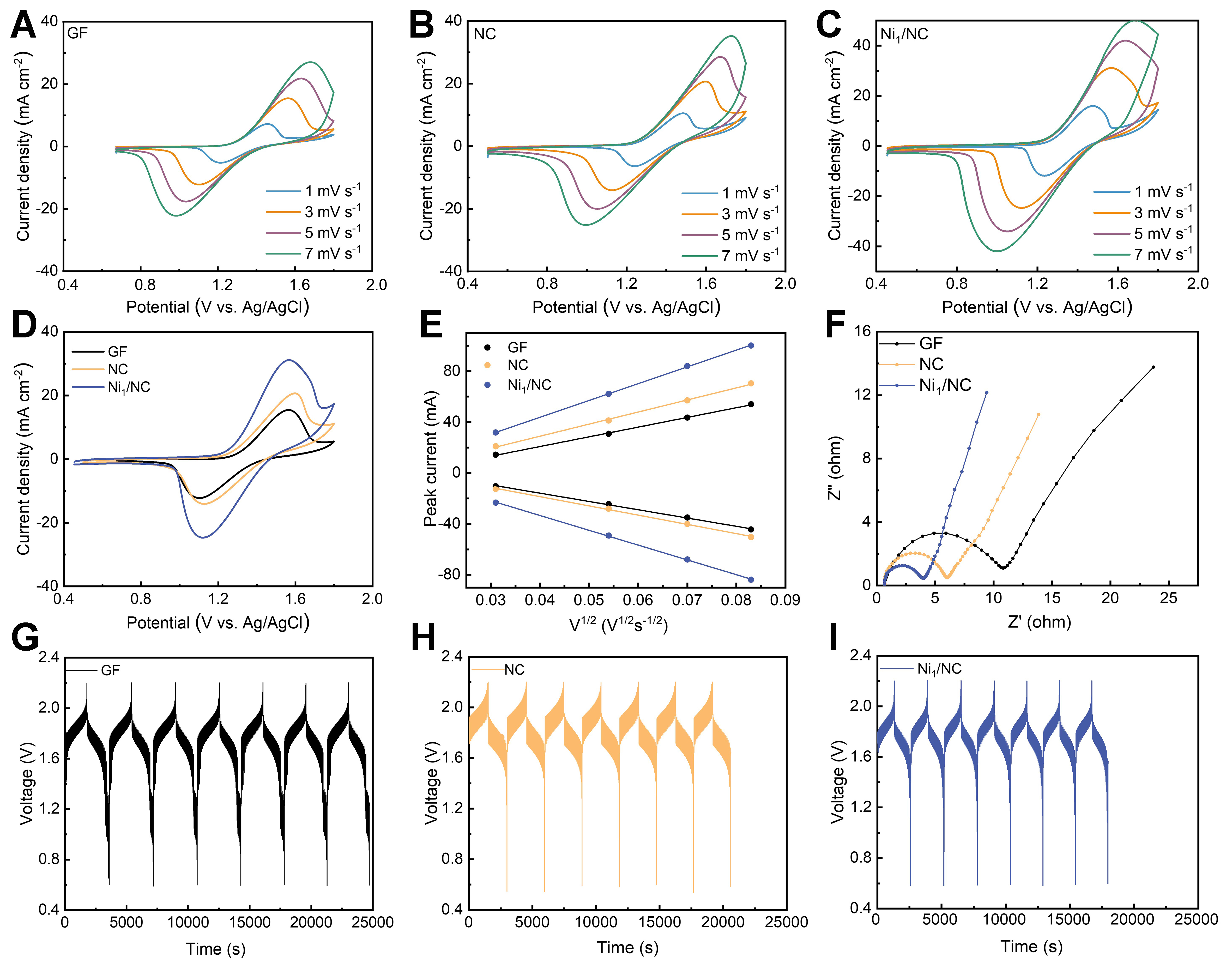
Figure 3. CV curves of (A) GF, (B) NC, and (C) Ni1/NC; (D) CV curves of Ni1/NC, NC, and GF at a scan rate of 3 mV s-1; (E) Peak current density vs. the square root of scan rate derived from the CV curves in (D); (F) Nyquist plots of Ni1/NC, NC, and GF (measured at open circuit potential); (G-I) Voltage profiles vs. time for the GF, NC, and Ni1/NC electrodes at 80 mA cm-2. CV: Cyclic voltammetry; GF: graphite felt; NC: nitrogen-doped carbon.
where Ip is in A cm-2, n = 1, A (cm2) is the electroactive surface area, C (mol L-1) is the bulk concentration of the redox mediator, D0 (cm2 s-1) is the diffusion coefficient, and ν (V s-1) is the scan rate. The excellent linearity observed in the Ip vs. ν1/2 plots unambiguously confirms the diffusion-controlled nature of the redox process. Moreover, the steeper slope over Ni1/NC electrode affords a higher apparent diffusion coefficient (D0 = 2.06 × 10⁻³ cm2 s-1) than those over GF (D0 = 6.16 × 10⁻⁴ cm2 s-1) and pristine NC (D0 = 1.02 × 10⁻³ cm2 s-1), suggesting accelerated mass transport.
Figure 3F displays the Nyquist plots obtained from PEIS measurements for the Ni1/NC, NC, and GF electrodes. The Ni1/NC electrode exhibits a markedly lower charge transfer resistance (Rct = 3.7 Ω) compared to the NC (5.6 Ω) and GF (11.0 Ω) electrodes. The smaller Rct value over the Ni1/NC electrode is consistent with the decreased overpotential observed in the CV measurements, confirming that Ni1/NC-modification significantly facilitates charge transfer kinetics. The nanostructured catalyst layer is also believed to increase the effective surface area of the electrode, thereby promoting ion diffusion[39].
To confirm it, GITT measurements were conducted at 80 mA cm-2, as shown in Figure 3G-I and Supplementary Figure 10. The Ni1/NC electrode exhibited smooth voltage changes and minimal polarization during the current pulses, indicating superior charge transfer properties. In contrast, the GF, NC, and its Ni nanoparticle counterpart (NiNP/NC) electrodes exhibited more pronounced voltage changes and polarization. The calculated ion diffusion coefficient (D) for Ni1/NC (0.0035 cm2 s-1) was significantly higher than those for the NC (0.0020 cm2 s-1), GF (0.0016 cm2 s-1), and NiNP/NC (0.0017 cm2 s-1) electrodes, further confirming the enhanced ion transport kinetics within the Ni1/NC-based electrode system.
RFB performance
To demonstrate the practical applicability of the catalysts, V-Ce redox flow cells were assembled using Ni1/NC, NC, and GF as the positive electrode and pristine GF as the negative electrode. Energy efficiency (EE), defined as the product of coulombic efficiency (CE) and voltage efficiency (VE) (EE = CE × VE), serves as a key indicator of energy conversion and storage capability during charge-discharge cycling[40,41]. The rate performance of the flow cells is presented in Figure 4A and Supplementary Figure 11. As the current density increased from 40 to 200 mA cm-2, the increasing overpotential and polarization caused a decreasing EE for all cells. Nevertheless, the cell with the Ni1/NC electrode achieved a high EE of 69.1% at 200 mA cm-2, significantly surpassing those of NC (53.8%), NiNP/NC (62.4%), and GF (47.3%). This superior performance primarily stems from the enhanced catalytic activity of the Ni1/NC catalyst, which accelerates the reaction kinetics and charge diffusion. When the current density was reduced from 200 to 80 mA cm-2, the EE of the Ni1/NC cell rapidly recovered to its previous level. The rapid recovery indicates lower polarization and higher inherent reversibility on the Ni1/NC electrode[42]. In contrast, cells with NC, NiNP/NC, and NC electrodes show limited recovery capability.
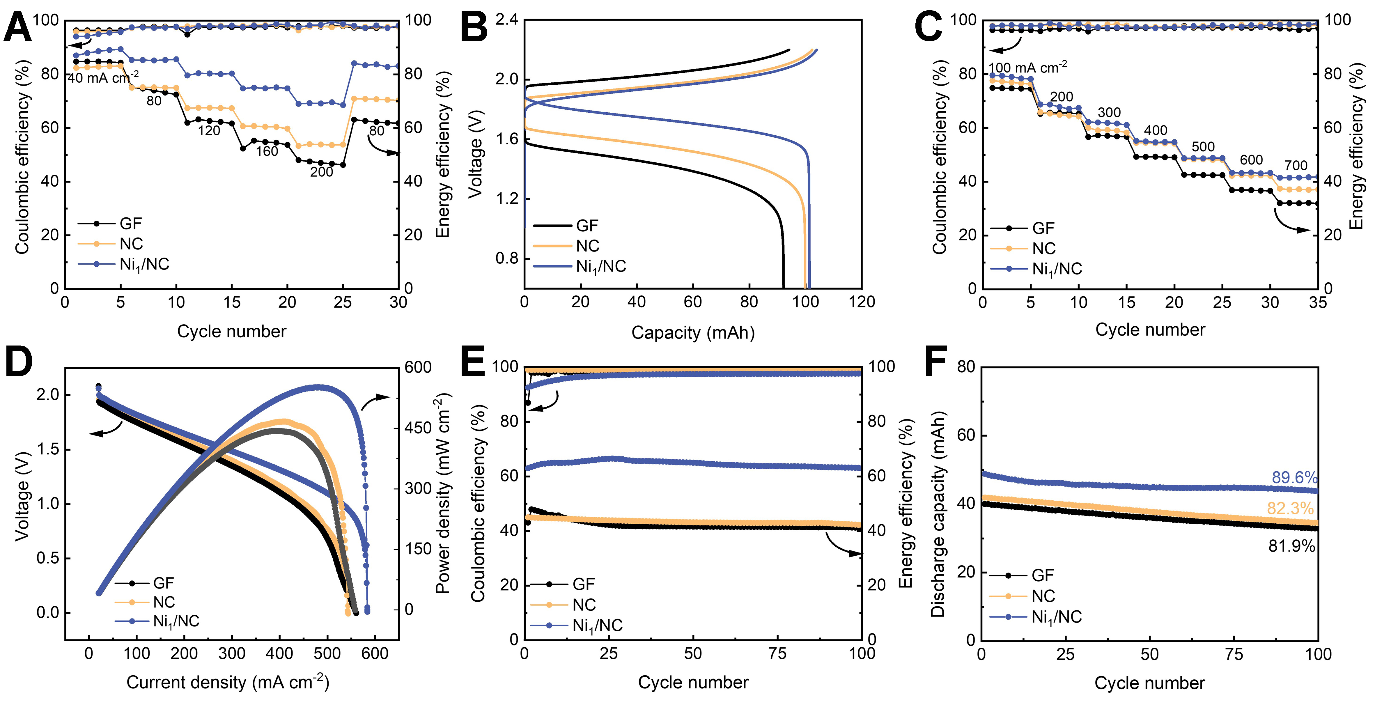
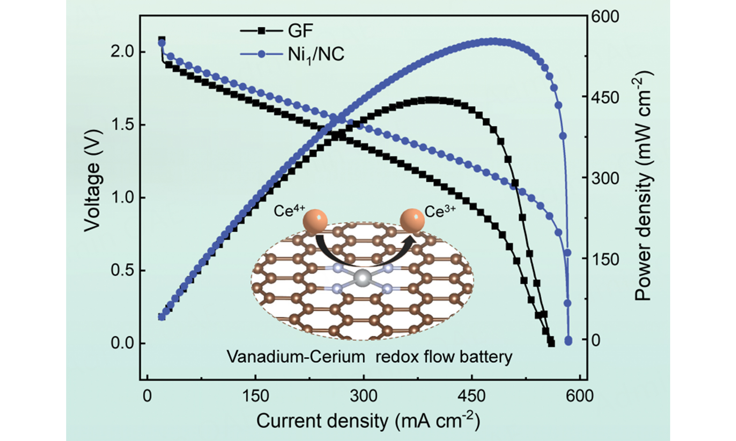
Figure 4. RFB performances. (A) Coulombic and energy efficiencies vs. cycle number of Ni1/NC, NC, and GF at various current densities; (B) Voltage profiles vs. capacity of Ni1/NC, NC, and GF at a current density of 80 mA cm-2; (C) CE and EE profiles of Ni1/NC, NC, and GF charged at 80 mA cm-2 and discharged under high current densities ranging from 100 to 700 mA cm-2; (D) Voltage and power density curves vs. current density of Ni1/NC, NC, and GF; (E and F) Long-term cycling stability of Ni1/NC, NC, and GF at 200 mA cm-2. RFB: Redox flow battery; NC: nitrogen-doped carbon; GF: graphite felt; CE: coulombic efficiency; EE: energy efficiency.
The charge-discharge profiles at 80 mA cm-2 are presented in Figure 4B. Among the tested materials, Ni1/NC exhibits the most favorable voltage characteristics - markedly lower charging potential, higher discharging potential, and significantly enhanced capacity. This improvement is directly attributable to the superior electrocatalytic activity of the Ni1/NC electrode towards the Ce3+/Ce4+ redox reaction, which effectively reduces the reaction overpotential[43,44]. Figure 4C displays the CE and EE of the three cells charged at
Long-term cycling stability was then evaluated by subjecting it to cycling 100 times at 200 mA cm-2 [Figure 4E and F]. The cell with Ni1/NC electrode maintains a high EE (65.1%) throughout the cycling test, demonstrating its satisfactory stability. Moreover, it also delivers a high capacity of 48.8 mAh and a remarkable capacity retention rate of 89.6% after 100 cycles, significantly superior to that of cells with NC (41.8 mAh, 82.3% retention), NiNP/NC (44.5 mAh, 80.8% retention), and GF (40.0 mAh, 81.9% retention) electrodes. The excellent durability of cell with Ni1/NC electrode stems from the chemical stability of Ni1/NC catalyst in high current densities and strong acidic conditions, effectively mitigating the degradation processes of the cell. Moreover, the battery with Ni1/NC electrodes also exhibited superior battery performance to those reported in most literature [Supplementary Table 3].
To further verify the structural and chemical robustness of the Ni1/NC catalyst, comprehensive post-cycling characterizations were performed. SEM images [Supplementary Figure 12] show that the Ni1/NC coating adheres firmly to the GF after long-term cycling. TEM and HAADF-STEM images [Supplementary Figure 13A and B] reveal there are no noticeable structural collapse or metal aggregation on Ni1/NC catalyst. EDS mapping [Supplementary Figure 13C] demonstrates a uniform distribution of Ni and N elements and the Ni loading is similar to that of fresh catalysts. Further inductively coupled plasma optical emission spectroscopy (ICP-OES) analysis [Supplementary Table 4] also confirmed that the loss rate of Ni in Ni1/NC catalyst was only 0.71 wt% after long-term cycling. XPS analysis [Supplementary Figure 14] further corroborates the chemical stability, despite the interference from F KLL Auger peaks (from the Nafion binder in preparing electrode), the core Ni-N coordination environment is well-preserved, as evidenced by the stable Ni 2p3/2 position and the persistent Ni-Nx signature in the N 1s spectrum. Moreover, online DEMS was employed to monitor gas evolution during operation [Supplementary Figure 15]. Compared to the pristine GF, the Ni1/NC electrode exhibits significantly suppressed CO2 evolution, indicating that the Ni1/NC catalyst effectively mitigates carbon corrosion at high oxidative potentials. These results collectively demonstrate the exceptional morphological and chemical integrity of the Ni1/NC catalyst, ensuring its long-term reliability in V-Ce RFBs.
Theoretical calculation analysis
DFT calculations were performed to unravel the origin of the exceptional electrocatalytic activity of Ni1/NC toward the Ce3+/Ce4+ redox couple. The Ni–N4 structural model [Figure 5A] was constructed based on the experimentally determined coordination number (3.8) and bond distance (1.95 Å) from EXAFS fitting. The thermodynamic stability of this moiety was subsequently confirmed by a calculated formation energy of -1.27 eV [Supplementary Figure 16]. Differential charge density analysis reveals pronounced electron depletion at the Ni center, and Bader charge quantification [Supplementary Table 5] indicates a transfer of 1.03 e- from Ni to the N-doped carbon framework, and imparting strong Lewis acidity to the Ni site, thereby promoting the adsorption of Ce3+/Ce4+ species[45]. Figure 5B illustrates the dehydration process of [Ce(H2O)9]3+, in which the strongly Lewis-acidic Ni atom effectively competes with water and weakens the Ce–OH2 bonds, disrupts the original stable nine-coordinate structure of Ce3+, and exposes the metal center for direct electron transfer, thus endowing the Ni–N4 site with excellent oxidative activity[46,47].
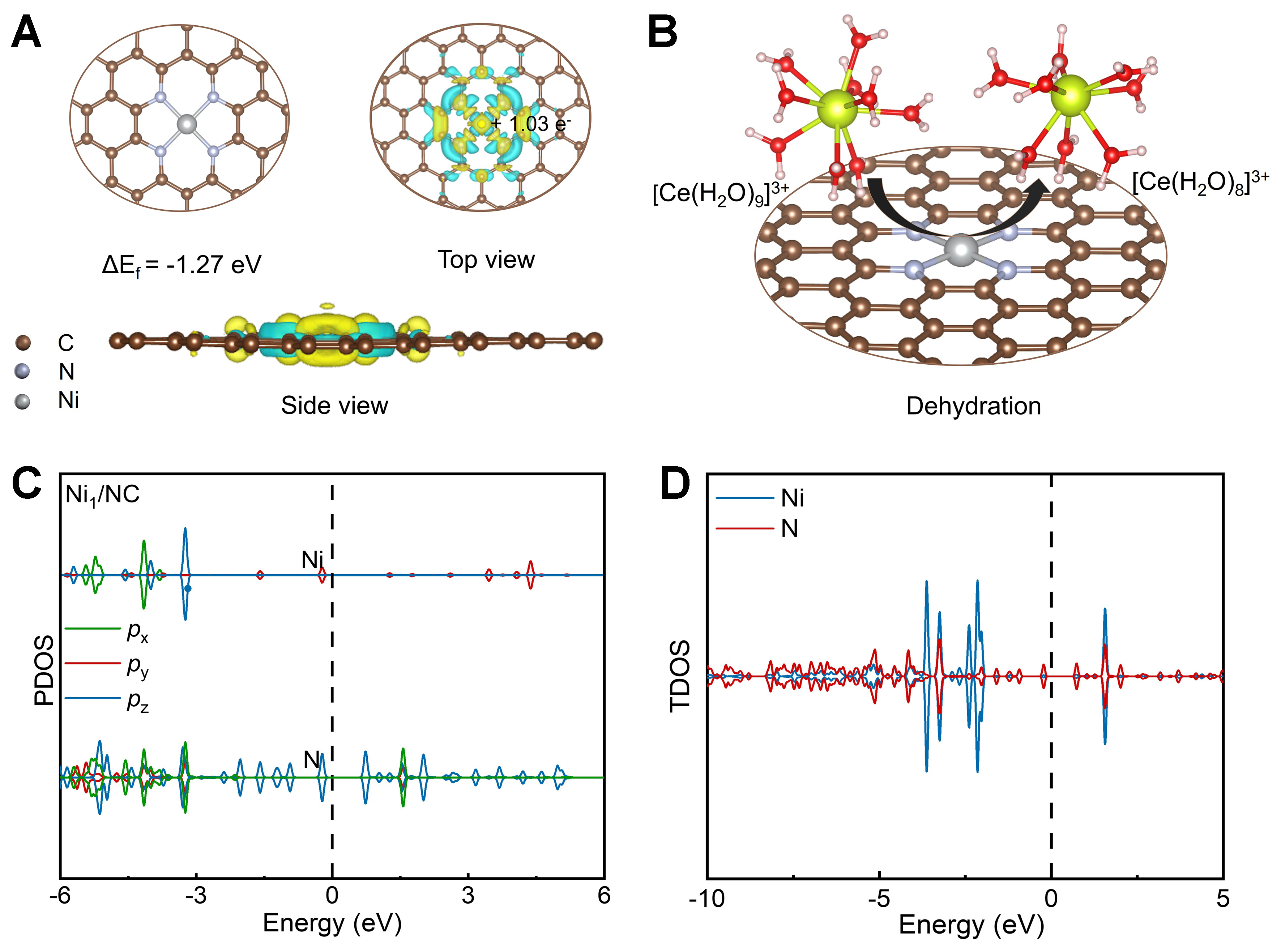
Figure 5. Theoretical calculations of Ni1/NC. (A) Optimized Ni–N4 configuration (the formation energy is -1.24 eV) and differential charge analysis of Ni1/NC. The yellow and cyan iso-surfaces represent areas of electron enrichment and deficiency, respectively; (B) Schematic of the dehydration process from [Ce(H2O)9]3+ to [Ce(H2O)8]3+; (C) PDOS and (D) TDOS of Ni1/NC. NC: Nitrogen-doped carbon; PDOS: projected density of states; TDOS: total density of states.
The projected density of states [Figure 5C] reveals that the out-of-plane 3dz2 orbital of Ni dominates with a sharp peak straddling the Fermi level, accompanied by substantial unoccupied states. In contrast, the in-plane d-orbitals are deeply occupied, forming a highly anisotropic electronic structure which is conducive to axial interaction with Ce species[48]. Meanwhile, the total density of states [Figure 5D] displays a symmetric spin distribution, indicating a non-magnetic ground state for the Ni1/NC system. Despite the lack of net spin polarization, the Ni 3d orbitals exhibit significant hybridization with N-derived states near the Fermi level, creating a coordinatively unsaturated and electronically active environment. Notably, the states near the Fermi level are predominantly contributed by the Ni center and span a broad energy range, reflecting strong Ni–N coupling and high electron delocalization that effectively accelerate bidirectional electron transfer[49]. Collectively, these electronic and structural features account for the excellent electrocatalytic activity of the Ni1/NC catalyst.
CONCLUSIONS
A single atomic Ni catalyst with a Ni1–N4 moiety on NC support has been successfully synthesized and used as advanced positive electrodes for high-performance V-Ce RFBs. Owing to the abundant accessible active sites and unique structural properties of Ni1/NC for catalysis, Ni1/NC-modified electrode exhibited significantly enhanced kinetics for the Ce3+/Ce4+ redox reaction and significantly improved overall performance for practical V-Ce RFBs compared to NC-modified and pristine GF electrodes. These improvements are attributed to the unique electronic structure of the Ni1–N4 sites, which facilitate charge transfer and enhance activation of reactant species (Ce4+), as elucidated by DFT calculations. This work demonstrates the effectiveness of SACs in enhancing the performance of V-Ce RFBs and sheds light on the design of advanced electrocatalysts.
DECLARATIONS
Acknowledgments
The authors acknowledge the financial supports from the Natural Science Foundation of Jiangxi, China (20232ACB203002) and the National Natural Science Foundation of China (22502210). The authors also thank Dr. Jianrong Zeng and the BL13SSW beamline at the Shanghai Synchrotron Radiation Facility (https://cstr.cn/31124.02.SSRF.BL13SSW) for the XAFS experiments supports.
Authors’ contributions
Conceptualization, investigation, and writing: Wang, L.; Qi, H.; Ye, C.; Liu, B.; Zeng, D.; Ji, Z.; Huang, X.; Chen, W.; Pan, J. H.
Supervision: Huang, X.; Chen, W.; Pan, J. H.
Availability of data and materials
The original contributions presented in this study are included in the article/Supplementary Materials. Further inquiries can be directed to the corresponding authors.
AI and AI-assisted tools statement
During the preparation of this manuscript, the AI tool DeepSeek-R1 (version 1.0, released 2025-01-20) was used solely for language editing. The tool did not influence the study design, data collection, analysis, interpretation, or the scientific content of the work. All authors take full responsibility for the accuracy, integrity, and final content of the manuscript.
Financial support and sponsorship
This work was supported by the Natural Science Foundation of Jiangxi, China (20232ACB203002) and the National Natural Science Foundation of China (22502210 and 22461142141).
Conflicts of interest
All authors declared that there are no conflicts of interest.
Ethical approval and consent to participate
Not applicable.
Consent for publication
Not applicable.
Copyright
© The Author(s) 2026.
Supplementary Materials
REFERENCES
2. Armstrong, R. C.; Wolfram, C.; de Jong, K. P.; et al. The frontiers of energy. Nat. Energy. 2016, 1, 15020.
3. Noack, J.; Roznyatovskaya, N.; Herr, T.; Fischer, P. The chemistry of redox-flow batteries. Angew. Chem. Int. Ed. Engl. 2015, 54, 9776-809.
4. Liu, Y.; Niu, Y.; Ouyang, X.; et al. Progress of organic, inorganic redox flow battery and mechanism of electrode reaction. Nano. Res. Energy. 2023, 2, e9120081.
5. Jiang, H.; Sun, J.; Wei, L.; Wu, M.; Shyy, W.; Zhao, T. A high power density and long cycle life vanadium redox flow battery. Energy. Storage. Mater. 2020, 24, 529-40.
6. Ye, L.; Qi, S.; Cheng, T.; et al. Vanadium redox flow battery: review and perspective of 3D electrodes. ACS. Nano. 2024, 18, 18852-69.
7. Huang, Z.; Mu, A.; Wu, L.; Yang, B.; Qian, Y.; Wang, J. Comprehensive analysis of critical issues in all-vanadium redox flow battery. ACS. Sustain. Chem. Eng. 2022, 10, 7786-810.
8. Lourenssen, K.; Williams, J.; Ahmadpour, F.; Clemmer, R.; Tasnim, S. Vanadium redox flow batteries: a comprehensive review. J. Energy. Storage. 2019, 25, 100844.
9. Ulaganathan, M.; Aravindan, V.; Yan, Q.; Madhavi, S.; Skyllas‐Kazacos, M.; Lim, T. M. Recent advancements in all‐vanadium redox flow batteries. Adv. Mater. Inter. 2016, 3, 1500309.
10. Wu, Y.; Zhou, L.; Xie, Y.; et al. A green europium-cerium redox flow battery with ultrahigh voltage and high performance. Chem. Eng. J. 2024, 500, 157189.
11. Jelinek, L.; Wei, Y.; Mikio, K. Electro-oxidation of concentrated Ce(III) at carbon felt anode in nitric acid media. J. Rare. Earths. 2006, 24, 257-63.
12. Zhang, X.; Liu, L.; Zhang, K.; et al. Modulating single-atom sulfur-vacancy defect in MoS2-x catalysts to boost cathode redox kinetics for vanadium flow batteries. Energy. Storage. Mater. 2024, 69, 103442.
13. Hosseini, M. G.; Mousavihashemi, S.; Murcia-López, S.; Flox, C.; Andreu, T.; Morante, J. R. High-power positive electrode based on synergistic effect of N- and WO3-decorated carbon felt for vanadium redox flow batteries. Carbon 2018, 136, 444-53.
14. Xing, F.; Liu, T.; Yin, Y.; et al. Highly active hollow porous carbon spheres@graphite felt composite electrode for high power density vanadium flow batteries. Adv. Funct. Mater. 2022, 32, 2111267.
15. Jiang, Y.; Wang, Y.; Cheng, G.; et al. Multiple‐dimensioned defect engineering for graphite felt electrode of vanadium redox flow battery. Carbon. Energy. 2024, 6, e537.
16. Gong, W.; Yuan, Q.; Chen, C.; et al. Liberating N-CNTs confined highly dispersed Co–Nx sites for selective hydrogenation of quinolines. Adv. Mater. 2019, 31, e1906051.
17. Na, Z.; Wang, X.; Liu, X.; Li, W.; Sun, X. O/N/S trifunctional doping on graphite felts: a novel strategy toward performance boosting of cerium‐based redox flow batteries. Carbon. Energy. 2021, 3, 752-61.
18. Qiao, B.; Wang, A.; Yang, X.; et al. Single-atom catalysis of CO oxidation using Pt1/FeOx. Nat. Chem. 2011, 3, 634-41.
19. Kaiser, S. K.; Chen, Z.; Faust Akl, D.; Mitchell, S.; Pérez-Ramírez, J. Single-atom catalysts across the periodic table. Chem. Rev. 2020, 120, 11703-809.
20. Yang, X. F.; Wang, A.; Qiao, B.; Li, J.; Liu, J.; Zhang, T. Single-atom catalysts: a new frontier in heterogeneous catalysis. Acc. Chem. Res. 2013, 46, 1740-8.
21. Wang, A.; Li, J.; Zhang, T. Heterogeneous single-atom catalysis. Nat. Rev. Chem. 2018, 2, 65-81.
22. Xing, F.; Wang, S.; Fu, Q.; Liu, T.; Li, X. Heteroatom-tuned Bi pz-orbital hybridization of single-atom catalysts for high-power density vanadium flow batteries. Energy. Storage. Mater. 2025, 81, 104472.
23. Wang, Z.; Lu, G.; Wei, T.; et al. Synergy of single atoms and sulfur vacancies for advanced polysulfide-iodide redox flow battery. Nat. Commun. 2025, 16, 2885.
24. Xing, F.; Fu, Q.; Xing, F.; et al. Bismuth single atoms regulated graphite felt electrode boosting high power density vanadium flow batteries. J. Am. Chem. Soc. 2024, 146, 26024-33.
25. Huang, J.; He, G.; Huang, K.; et al. Atomic iron on porous graphene films for catalyzing the VO2+/VO2+ redox couple in vanadium redox flow batteries. Mater. Today. Phys. 2023, 35, 101117.
26. Hai, X.; Xi, S.; Mitchell, S.; et al. Scalable two-step annealing method for preparing ultra-high-density single-atom catalyst libraries. Nat. Nanotechnol. 2022, 17, 174-81.
27. Chen, W.; Jin, H.; He, F.; Cui, P.; Cao, C.; Song, W. Dynamic evolution of nitrogen and oxygen dual-coordinated single atomic copper catalyst during partial oxidation of benzene to phenol. Nano. Res. 2022, 15, 3017-25.
28. Grimme, S.; Ehrlich, S.; Goerigk, L. Effect of the damping function in dispersion corrected density functional theory. J. Comput. Chem. 2011, 32, 1456-65.
29. Perdew, J. P.; Burke, K.; Ernzerhof, M. Generalized gradient approximation made simple. Phys. Rev. Lett. 1996, 77, 3865-8.
30. Kresse, G.; Joubert, D. From ultrasoft pseudopotentials to the projector augmented-wave method. Phys. Rev. B. 1999, 59, 1758-75.
31. Freysoldt, C.; Grabowski, B.; Hickel, T.; et al. First-principles calculations for point defects in solids. Rev. Mod. Phys. 2014, 86, 253-305.
32. Kresse, G.; Furthmüller, J. Efficient iterative schemes for ab initio total-energy calculations using a plane-wave basis set. Phys. Rev. B. Condens. Matter. 1996, 54, 11169-86.
33. Gawande, M. B.; Fornasiero, P.; Zbořil, R. Carbon-based single-atom catalysts for advanced applications. ACS. Catal. 2020, 10, 2231-59.
34. Santhosh Kumar, R.; Vijayapradeep, S.; Sakthivel, V.; Sayfiddinov, D.; Kim, A. R.; Yoo, D. J. Foam-like porous structured trimetal electrocatalysts exhibiting superior performance for overall water splitting and solid-liquid zinc-air batteries. ACS. Appl. Mater. Interfaces. 2025, 17, 10556-69.
35. Kumar, R. S.; Mannu, P.; Prabhakaran, S.; et al. Trimetallic oxide electrocatalyst for enhanced redox activity in zinc-air batteries evaluated by in situ analysis. Adv. Sci. 2023, 10, e2303525.
36. Chen, W.; Che, Y.; Xia, J.; et al. Metal-sulfur interfaces as the primary active sites for catalytic hydrogenations. J. Am. Chem. Soc. 2024, 146, 11542-52.
37. Wu, J.; Cao, X.; Ji, Y.; et al. Boosting kinetics of Ce3+/Ce4+ redox reaction by constructing TiC/TiO2 heterojunction for cerium‐based flow batteries. Adv. Funct. Mater. 2024, 34, 2309825.
38. Deng, Q.; Huangyang, X.; Zhang, X.; et al. Edge‐rich multidimensional frame carbon as High‐Performance Electrode Material For Vanadium Redox Flow Batteries. Adv. Energy. Mater. 2022, 12, 2103186.
39. Yuan, Z.; Liu, X.; Xu, W.; Duan, Y.; Zhang, H.; Li, X. Negatively charged nanoporous membrane for a dendrite-free alkaline zinc-based flow battery with long cycle life. Nat. Commun. 2018, 9, 3731.
40. Park, M.; Ryu, J.; Wang, W.; Cho, J. Material design and engineering of next-generation flow-battery technologies. Nat. Rev. Mater. 2017, 2, 16080.
41. Zhang, L.; Jia, Y.; Liu, H.; et al. Charge polarization from atomic metals on adjacent graphitic layers for enhancing the hydrogen evolution reaction. Angew. Chem. Int. Ed. Engl. 2019, 58, 9404-8.
42. Jiang, Y.; Liu, Z.; Lv, Y.; et al. Perovskite enables high performance vanadium redox flow battery. Chem. Eng. J. 2022, 443, 136341.
43. Li, B.; Nie, Z.; Vijayakumar, M.; et al. Ambipolar zinc-polyiodide electrolyte for a high-energy density aqueous redox flow battery. Nat. Commun. 2015, 6, 6303.
44. Zhang, X.; Valencia, A.; Li, W.; et al. Decoupling activation and transport by electron-regulated atomic-Bi harnessed surface-to-pore interface for vanadium redox flow battery. Adv. Mater. 2024, 36, e2305415.
45. Guo, J.; Pan, L.; Sun, J.; et al. Metal‐free fabrication of nitrogen‐doped vertical graphene on graphite felt electrodes with enhanced reaction kinetics and mass transport for high‐performance redox flow batteries. Adv. Energy. Mater. 2024, 14, 2302521.
46. Koppe, J.; Yakimov, A. V.; Gioffrè, D.; et al. Coordination environments of Pt single-atom catalysts from NMR signatures. Nature 2025, 642, 613-9.
47. Liu, Z.; Sun, Y.; Wang, Y.; et al. Optimal solution for modeling electrocatalysis on two-dimensional single-atom catalysts with grand canonical DFT. ACS. Catal. 2025, 15, 7993-8004.
48. Zhao, X.; Wang, F.; Kong, X. P.; Fang, R.; Li, Y. Dual-metal hetero-single-atoms with different coordination for efficient synergistic catalysis. J. Am. Chem. Soc. 2021, 143, 16068-77.
Cite This Article
How to Cite
Download Citation
Export Citation File:
Type of Import
Tips on Downloading Citation
Citation Manager File Format
Type of Import
Direct Import: When the Direct Import option is selected (the default state), a dialogue box will give you the option to Save or Open the downloaded citation data. Choosing Open will either launch your citation manager or give you a choice of applications with which to use the metadata. The Save option saves the file locally for later use.
Indirect Import: When the Indirect Import option is selected, the metadata is displayed and may be copied and pasted as needed.
About This Article
Special Topic
Copyright

Data & Comments
Data
0


Comments
Comments must be written in English. Spam, offensive content, impersonation, and private information will not be permitted. If any comment is reported and identified as inappropriate content by OAE staff, the comment will be removed without notice. If you have any queries or need any help, please contact us at [email protected].