


A hemispherical triboelectric nanogenerator for continuous droplet energy harvesting via electret field-driven polarization
 0
0 Abstract
Harvesting energy from water droplets offers a promising route to power decentralized electronics, yet conventional triboelectric nanogenerators (TENGs) are limited by intermittent output and reliance on repetitive mechanical contact. Here, we present a hemispherical TENG (H-TENG) featuring a breakthrough dual-electrode configuration that enables high-efficiency continuous energy extraction from a single moving droplet. The device operates via a two-phase mechanism: initial contact electrification followed by sustained electret-field-driven polarization. As the droplet oscillates, the friction layer accumulates charges and evolves into a permanent electret, producing a stable electric field that polarizes subsequent droplets without direct contact. This design eliminates the inherent intermittency of conventional TENGs and allows infinite energy conversion cycles under wave-like motion. The hemispherical structure is ideally suited for scalable blue energy harvesting from ocean waves. Through systematic experimental and theoretical analysis, we demonstrate the essential roles of droplet kinetics, ion-mediated interfacial effects, and optimized device geometry in enhancing performance. This work offers a robust, material - structure-integrated strategy toward sustainable droplet-based energy harvesting, with significant potential for applications in self-powered marine systems and large-scale renewable energy conversion.
Keywords
INTRODUCTION
The rapid expansion of the Internet of Things (IoT) and the growing deployment of distributed environmental sensors have intensified the demand for sustainable, decentralized power sources[1]. Traditional batteries and supercapacitors face limitations in lifespan, maintenance, and ecological sustainability, particularly in remote or large-scale applications. Energy harvesting technologies that leverage ambient energy sources - such as mechanical vibrations, wind, solar, and water waves - offer a promising alternative for powering micro- and nano-electronics continuously and autonomously[2]. Among these, water droplets represent a widespread and abundant energy source, from raindrops to ocean waves, yet their potential remains underexplored due to limitations in existing energy conversion mechanisms[3-5].
Triboelectric nanogenerators (TENGs) have emerged as a leading technology for converting mechanical energy into electricity via contact electrification and electrostatic induction[6,7]. Conventional liquid-solid TENGs, which often operate in single-electrode mode, rely on intermittent droplet contact and separation events to generate transient current signals[4]. While conceptually viable, these systems suffer from inherent drawbacks: discontinuous output, low energy conversion efficiency, and reliance on repeated physical contact - factors that severely limit their practical applicability[4]. Moreover, their performance is highly sensitive to ion concentration in water, further constraining real-world deployment in diverse aqueous environments[4,6].
To overcome these challenges, we report a hemispherical triboelectric nanogenerator (H-TENG) with a groundbreaking dual-electrode architecture, engineered to enable efficient and continuous energy harvesting from moving water droplets. The device incorporates a bottom electrode beneath a poly(vinylidene fluoride-co-hexafluoropropylene) [P(VDF-HFP)] friction layer and a strategically positioned surface electrode on the same layer, facilitating a two-stage energy generation mechanism. Initially, energy is harvested through conventional contact electrification. However, after repeated droplet motions, the friction layer accumulates substantial negative charges and evolves into a robust electret - a permanently charged material that generates a sustained electric field. This field polarizes incoming droplets, triggering continuous charge separation and energy generation without the need for direct physical contact, thereby overcoming the fundamental intermittency of traditional TENGs.
The hemispherical design not only enhances droplet confinement and motion consistency but also enables the device to operate effectively under low-frequency, random wave motions - making it ideally suited for blue energy harvesting from ocean waves. When deployed in arrays, H-TENGs can form scalable networks that convert the vast and untapped kinetic energy of waves into continuous electrical output, offering a sustainable strategy for powering marine sensors, offshore installations, and distributed electronics. This work details the design, fabrication, and mechanistic underpinnings of the H-TENG, highlighting its transition from contact electrification to electret-dominated operation. We further demonstrate the influence of key parameters - such as droplet dynamics, ion concentration, and device geometry - on performance, supported by theoretical modeling and experimental validation. By integrating material innovation with structural and electrical design, the H-TENG represents a significant advance toward high-efficiency, continuous droplet-based energy harvesting, with broad implications for sustainable energy systems and self-powered electronics.
EXPERIMENTAL
Materials
Poly(vinylidene fluoride-co-hexafluoropropylene) [P(VDF-HFP)] particle was purchased from Aladdin. Sodium chloride (NaCl), potassium chloride (KCl), sodium bromide (NaBr), and potassium bromide (KBr) were supplied by Aladdin. N,N-dimethylformamide (DMF) was purchased from Titan Technology Co., Ltd. in Shanghai; tetrahydrofuran (THF) was procured from Macklin (Shanghai Macklin Biochemical Technology Co., Ltd.); conductive silver paste (8310) was sourced from Shenzhen Xinda Advanced Materials Co., Ltd.; insulating waterproof sealant (RTV 3140) was obtained from Dow Corning Corporation; transparent acrylic spherical shells (5 cm in diameter) and conductive copper tape were both purchased from online suppliers.
Fabrication of P(VDF-HFP) solutions
The P(VDF-HFP) spinning solution was prepared by dissolving P(VDF-HFP) powder in THF, DMF, or a DMF/THF mixture, respectively, and stirring at 60 °C for 12 h to form a transparent homogeneous solution. Subsequently, the solution was kept at room temperature for another 12 h to allow complete elimination of air bubbles from the spinning solution. P(VDF-HFP)/DMF solutions with mass percentages of 8%, 10%, 12%, 14%, 16%, and 18% were prepared. Additionally, a 10% mass percentage P(VDF-HFP) spinning solution was also prepared using THF and a DMF/THF mixture as solvents, respectively.
Fabrication of P(VDF-HFP) fiber mats
The hydrophobic P(VDF-HFP) mats were fabricated using the electrospinning technique. The equipment voltage was set at 14 kV, with a positive voltage of approximately 12.5 kV and a negative voltage of about 1.5 kV. The working distance was maintained at around 18 cm, and the feed rate was set at approximately 2 mL/h. Fine adjustments were made near this rate to achieve a stable Taylor cone. Meanwhile, the ambient temperature was controlled at 35 ± 1 °C and the relative humidity at 50%.
Using P(VDF-HFP) spinning solutions with a mass fraction of 10% and solvents including THF, DMF, and a DMF/THF mixture, electrospun fiber mats with varying microstructures were produced under the above electrospinning conditions. By employing P(VDF-HFP)/DMF spinning solutions at concentrations of 8%, 10%, 12%, 14%, 16%, and 18%, hydrophobic electrospun P(VDF-HFP) mats featuring a “microsphere-fiber interpenetrating structure” with distinct morphological characteristics were successfully prepared. Additionally, by varying the THF-to-DMF ratio in the mixed solvent, fibrous membranes with different morphological features could be fabricated.
Material characterizations
The morphology and chemical element distributions were characterized by scanning electron microscopy (Gemini 500). For the measurement of the electrical output capability of the TENG, external forces were applied by a stretching linear mechanical motor (LinMot). The open-circuit voltage (VOC), short circuit current (ISC), and short circuit charge transfer (QSC) were measured by keithley electrometer (keithley, 6514). The mechanical properties of hydrogels were measured by Universal stretching machine (ZBZX-JJ20190493, China). For all data involving error bars, the values are presented as mean ± standard deviation (SD). Three independent replicate experiments were performed for each condition (n = 3).
COMSOL model establishment for simulation
In this study, the electrostatic module of COMSOL Multiphysics was employed to simulate the electric potential distribution across various components of the model, with a focus on calculating the tribo-electrostatic polarization potential generated during the sliding motion of droplets of different volumes on a polymer dielectric film. The model comprises a P(VDF-HFP) triboelectric layer, top Cu electrode, and a geometric structure including a water droplet, all constructed and simulated using COMSOL Multiphysics. Triboelectric polarization occurs simultaneously at the interfaces between P(VDF-HFP) and the water droplet, as well as between P(VDF-HFP) and the Cu electrodes. Since the overall charge state of the system originates from triboelectric charge transfer, the total charge must remain electrically neutral. As the droplet moves, the charge distribution on both the droplet and the Cu electrodes changes dynamically. The surface charge density on P(VDF-HFP) was set to 10-8 C/m2[8]. Based on the actual dimensions, the model was constructed using geometric primitives such as rectangles and Boolean operations. A circular domain was introduced as an air layer, with a circular boundary layer serving as an infinite element domain. To simulate conditions at infinity, a Cartesian infinite element domain was incorporated. In the Electrostatics module of COMSOL, material properties - particularly relative permittivity - played a critical role: copper was assigned a relative permittivity of 99999 to emulate metallic electrostatic shielding, while P(VDF-HFP) and water were set to 3.4 and 5, respectively. Within the electrostatic field settings, the infinite element domain boundary was grounded to define the zero-potential reference, and surface charge density distributions were applied to corresponding components. A “Fine” physics-controlled mesh was used to improve computational accuracy. To simulate droplet movement, a parameter “k” was defined to control the position of the water droplet, and a parametric sweep was performed by varying “k”. Additionally, a piecewise function was introduced to accurately represent charge variations across different regions of the generator during operation.
RESULTS AND DISCUSSION
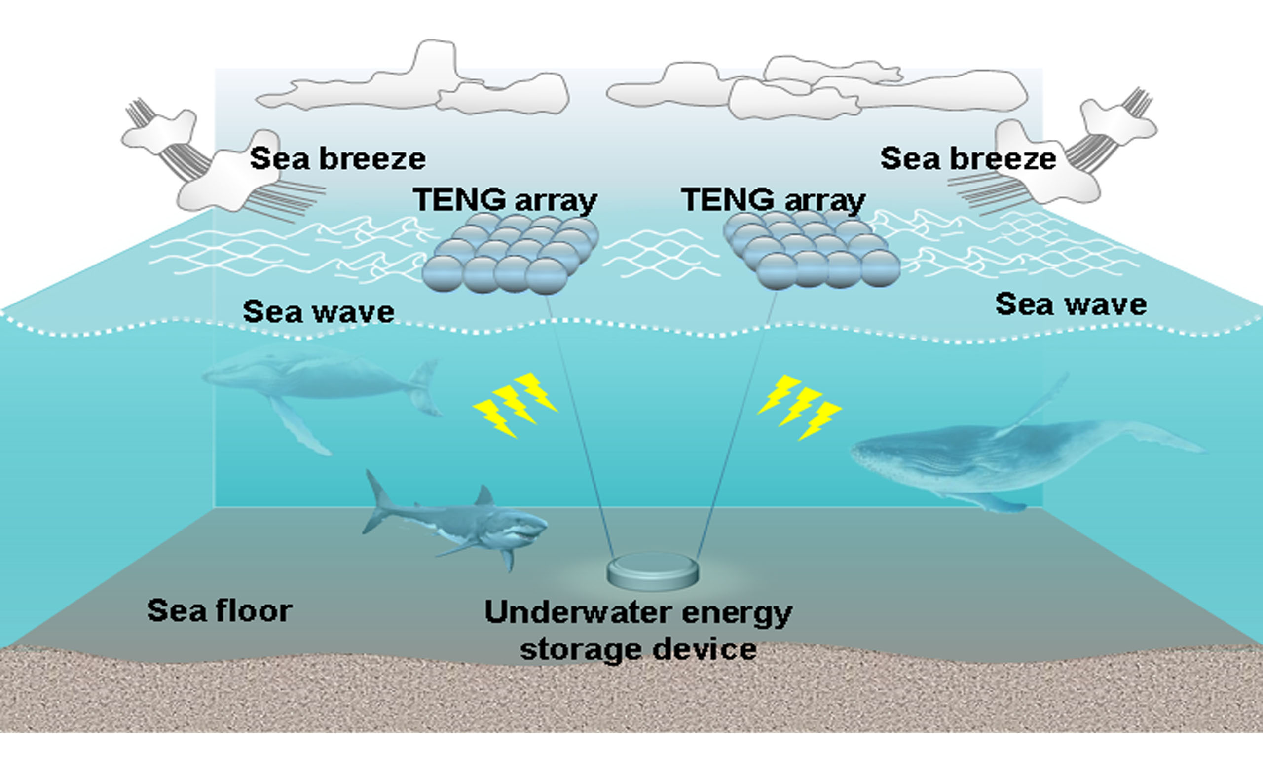
Figure 1A schematically illustrates a transformative application of the H-TENG: a large-scale TENG array deployed across the ocean surface to harness ubiquitous wave energy, often referred to as “blue energy”[9]. The concept visualizes numerous H-TENG units interconnected to form a flexible and scalable network, floating passively on the waves [Figure 1A]. The core innovation lies in leveraging the device’s unique hemispherical design. Each unit encapsulates a single water droplet, which is perpetually agitated by the gentle, random, and undulating motion of the waves. This motion drives the droplet into effectively infinite cycles of oscillation within the hemisphere, eliminating the need for an external mechanical energy source[10]. As described in the following mechanistic studies, each oscillation facilitates continuous energy conversion, initially through contact electrification and, more significantly, via the sustained electret-field-driven polarization after the charge saturation stage[11]. This process overcomes the fundamental limitation of intermittency that plagues conventional wave energy technologies. The array strategy transforms the vast, untapped kinetic energy of the ocean into a continuous and collective electrical output. This approach presents a promising, sustainable, and maintenance-friendly strategy for powering distributed electronics, large-scale marine sensor networks, and offshore installations, marking a significant leap towards practical and scalable blue energy harvesting.
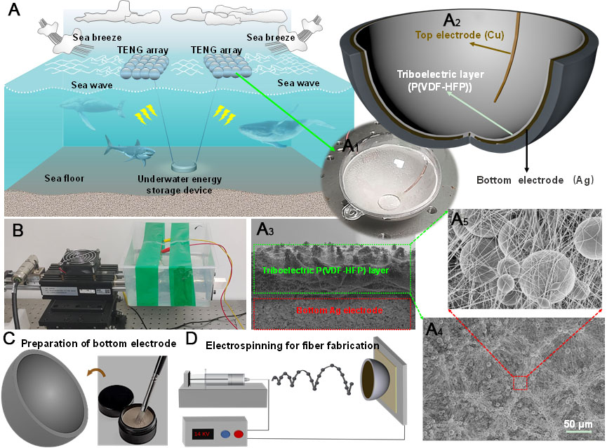
Figure 1. (A) Schematic illustration of a large-scale array of H-TENG devices deployed on the ocean surface for harvesting “blue energy” from wave motion. (A1) Photograph of the hemispherical triboelectric nanogenerator (H-TENG). (A2) Cross-sectional schematic diagram of the hemispherical triboelectric nanogenerator, clearly showing the bottom electrode (Ag), triboelectric layer [P(VDF-HFP)], and top electrode (Cu). SEM images of the device cross-section and the triboelectric layer microstructure: (A3) A cross-sectional view showing the distinct layers of the bottom Ag electrode and the triboelectric P(VDF-HFP) layer; (A4) An overview of the triboelectric layer’s morphology; (A5) A high-magnification image revealing a P(VDF-HFP) microstructure composed of fibers and spherical particles; (B) Photograph of the experimental setup for testing the device via laboratory-simulated wave motion; (C) Preparation of the bottom Ag electrode on the hemispherical substrate; (D) Electrospinning setup for depositing the P(VDF-HFP) nanofiber triboelectric layer. P(VDF-HFP): Poly(vinylidene fluoride-co-hexafluoropropylene); SEM: scanning electron microscopy; TENG: triboelectric nanogenerator; H-TENG: hemispherical TENG.
Figure 1A1 presents a photograph of the fully assembled H-TENG, showcasing its compact, integrated, and structurally robust design. The transparent or semi-transparent hemispherical shell allows for visual observation of the internal droplet motion, while its sealed structure ensures durability and reliable operation in various environments, particularly those involving water or humidity [Figure 1A1]. Figure 1A2 provides a detailed cross-sectional schematic diagram that clearly delineates the sophisticated multi-layer architecture of the H-TENG. The structure sequentially comprises: a bottom Ag electrode fabricated from a highly conductive material such as silver paste, which serves as one terminal for charge collection; a central triboelectric layer made of electrospun P(VDF-HFP), chosen for its excellent electron affinity and charge-trapping capabilities[12]; and a top electrode (Cu) strategically patterned on the surface of P(VDF-HFP) layer [Figure 1A2]. This innovative dual-electrode design on a single functional layer is a key innovation, enabling efficient charge exchange during the droplet’s motion.
Figure 1A3 is a cross-sectional Scanning Electron Microscopy (SEM) image that offers a clear, microscopic view of the well-defined interface and adhesion between the bottom Ag electrode and the overlying P(VDF-HFP) triboelectric layer. This image is crucial for verifying the integrity and uniformity of the deposited layers, which are essential for consistent device performance[12]. Figure 1A4 presents a lower-magnification SEM image providing an overview of the surface morphology of the electrospun P(VDF-HFP) triboelectric layer. This image reveals the large-scale, interconnected porous network formed by the nanofibers and sphere particles, which is critical for providing a large surface area for droplet contact and friction. Figure 1A5 is a high-magnification SEM image that reveals the intricate details of the P(VDF-HFP) layer’s microstructure. It shows a complex architecture consisting of a porous network of interwoven nanofibers decorated with spherical particles. This unique micro-nano hierarchical structure is not accidental but a result of optimized electrospinning parameters.
Figure 1B presents a photograph of the experimental setup designed to test the H-TENG’s performance under laboratory-simulated wave conditions. The system typically consists of a platform mounted on a mechanical shaker or actuator that replicates the gentle, random oscillatory motion of ocean waves. The H-TENG device is securely fixed to this platform, allowing a water droplet trapped inside to slosh rhythmically against the triboelectric layer and Cu electrode. Precision instruments, including a source meter or electrometer connected to the electrodes, are used to record the real-time electrical output generated by the droplet’s motion, validating the device’s efficacy in an environment mimicking its intended application. Figure 1C illustrates a key fabrication step: the preparation of the bottom Ag electrode on the concave hemispherical substrate. These processes ensure the conformal coating of a highly conductive, uniform, and adherent silver film onto the complex curved surface, forming a reliable foundational electrode for subsequent layers and efficient charge collection. Figure 1D schematically shows the electrospinning setup utilized to deposit the crucial P(VDF-HFP) nanofiber triboelectric layer. A high-voltage power supply is applied to a P(VDF-HFP) solution syringe, ejecting a fine jet of charged polymer solution towards the hemispherical substrate (which acts as the grounded collector). This process results in the deposition of a porous, non-woven mat of micro-to-nanoscale fibers, creating the high-surface-area, charge-trapping functional layer essential for enhanced triboelectrification[13]. Finally, all the experimental preparation and adjustment procedures are described in detail in the Experimental Section.
This comprehensive analysis focuses on the pivotal relationship between the polymer solution’s solid content (ranging from 8% to 18%) and the resulting microstructure of the electrospun P(VDF-HFP) films, which directly dictates the triboelectric performance of the H-TENG. The experiment involved preparing P(VDF-HFP) fiber mats by adjusting the ratio of THF/DMF mixed solvents. A higher proportion of the high-boiling-point solvent DMF resulted in more microsphere structures within the fibers, forming a microsphere-fiber interpenetrating network, while the low-boiling-point solvent THF favored the formation of smooth fibers [Supplementary Figure1]. The micro-nano rough structure synergizes with the inherent low surface energy of the material’s fluorine groups, collectively endowing the membrane with superhydrophobicity. The SEM image series [Figure 2A1-F3] provides a direct visual evolution of the film’s morphology. Increasing the spinning solution concentration promotes molecular chain entanglement and increases viscosity, leading to an increase in spherical particle diameter and a reduced number of microspheres.
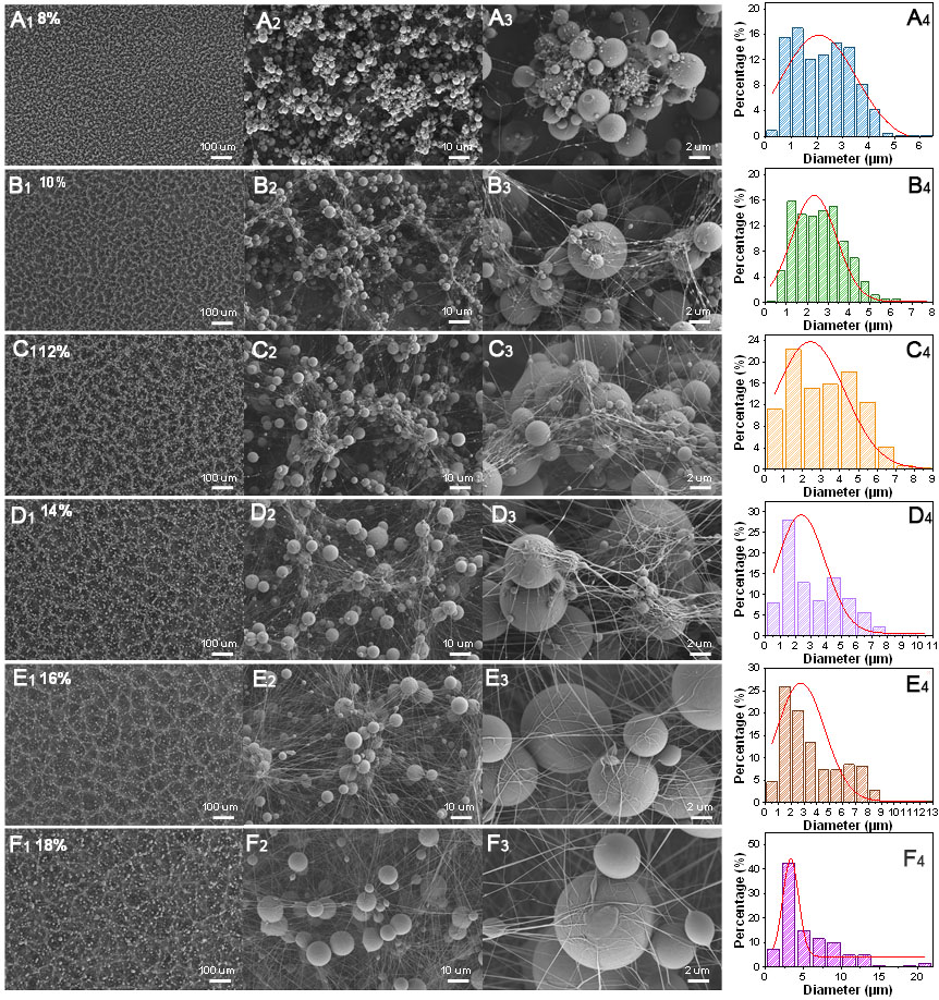
Figure 2. Microstructure morphology of the electrospun mats and the size distribution data of the spherical particles obtained with polymer solid content ranging from 8% to 18%. (A1-F3) SEM images of films prepared at 8%, 10%, 12%, 14%, 16% and 18% solid content, respectively; (A4-F4) Histogram of the corresponding particle size distribution. SEM: Scanning electron microscopy.
The corresponding particle size distribution histograms [Figure 2A4-F4] quantitatively corroborate the morphological trends observed in the SEM images. For films spun from lower concentration solutions (8%-10%), the histograms exhibit a relatively normal distribution, presenting a more uniform and narrower spread, which indicates the presence of more uniformly sized spherical beads [Figure 2A1-B3]. As the concentration increases to the 12%-14% range, the histograms display a bimodal distribution, featuring the emergence of both larger and smaller spherical particles [Figure 2C1-D3]. For the highest concentration samples (16%-18%), the particle size shifts significantly towards larger diameters, resulting in the prevalence of larger spherical particles [Figure 2E1-F3]. This statistical data on particle size distribution is crucial as it directly links processing parameters to a key material property: the surface-area-to-volume ratio. A higher density of finer features drastically increases this ratio, providing more active sites for contact electrification and enhancing the charge trapping capability, both of which are essential for high-performance triboelectric output. Furthermore, the porous nature of the optimal fibrous mat facilitates the adsorption and stabilization of ions from water droplets, critically influencing the formation of the electrical double layer (EDL) and, consequently, the final current output of the H-TENG device, as detailed in the following study’s mechanistic investigation.
Figure 3 provides a systematic evaluation of the hydrophobicity, mechanical properties, and morphological characteristics of the electrospun P(VDF-HFP) fiber mats. These properties are critical for ensuring the durability and triboelectric performance of the H-TENG under sustained operation. Figure 3A presents the water contact angle measurements of the electrospun films as a function of the solid content in the spinning solution. The curve clearly indicates that the contact angle decreases (indicating reduced hydrophobicity) with increasing polymer concentration. This trend is attributed to the evolution of surface morphology: lower solid content produce films with a higher density of fine fibers and microspheres, creating a hierarchical micro-nano roughness that enhances superhydrophobicity through air trapping. As the solid content increases, the surface topography transitions towards larger and fewer spherical particles (as shown in Figure 2), reducing the overall roughness and consequently the observed contact angle. This relationship directly links the processing parameter (solid content) to a key functional property (wettability), which influences droplet mobility and contact electrification efficiency. Additionally, as observed from the optical micrograph embedded in Figure 3A and the physical photograph in Supplementary Figure2, the polymer fiber mat not only exhibits excellent hydrophobicity toward DI water but also effectively repels various common liquids (including coffee, milk, orange juice, tea, and red ink), demonstrating exceptional universal hydrophobic properties. Figure 3B shows the stress-strain curves of electrospun fiber mats prepared from polymer solutions with concentrations ranging from 8 wt% to 18 wt%. The curves demonstrate a significant enhancement in mechanical robustness with increasing concentration. Mats from low-concentration solutions (8-10 wt%) exhibit lower fracture stress and strain, characteristic of weaker, less interconnected networks with more structural defects such as beads. In contrast, fibers from higher-concentration solutions (14-18 wt%) show markedly improved tensile strength and elongation at break. This enhancement is attributed to increased polymer chain entanglement and the consequent formation of a more coherent, densely packed fibrous network, which is essential for withstanding the repetitive mechanical stress imposed by the oscillating water droplet during long-term energy harvesting.
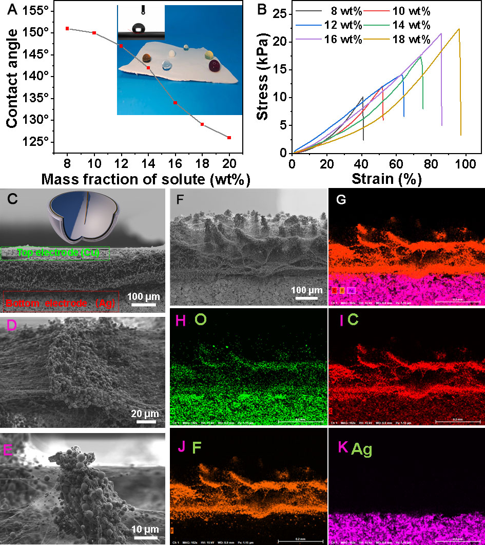
Figure 3. Hydrophobicity, mechanical and morphological characterization of the electrospun P(VDF-HFP) mats. (A) Contact angle curve of the electrospun fiber mats decreasing with the increasing solid content of the spinning solution; (B) Stress-strain curves of electrospun fiber mats with different polymer concentrations (8 wt% to 18 wt%; (C-E) High-magnification SEM images revealing the detailed surface texture and porosity of the optimal fiber mat; (F-K) Cross-sectional SEM image and elemental mapping of the triboelectric layer, clearly revealing the Ag electrode layer and the presence of C, O, and F in the triboelectric material layer. P(VDF-HFP): Poly(vinylidene fluoride-co-hexafluoropropylene); SEM: scanning electron microscopy.
Figure 3C-E present high-magnification SEM images that reveal the detailed surface texture and porosity of an optimally prepared fiber mat. These images highlight the complex interwoven architecture of nanofibers and embedded spherical particles, which create a high surface area and a porous, three-dimensional network. This structure is paramount for providing abundant active sites for contact electrification and facilitating efficient charge trapping[14,15]. Figure 3F-K comprise a cross-sectional SEM image and the corresponding elemental mapping (C, O, F) of the triboelectric layer. The cross-sectional view clearly delineates the distinct Ag electrode layer [Figure 3K] and the overlying P(VDF-HFP) triboelectric layer, confirming good interfacial adhesion and layer integrity - a prerequisite for stable electrical performance [Figure 3F]. As clearly observed from Figure 3F, the fiber mat surface possesses distinct microstructural features with varying undulations, which play a crucial role in enhancing its hydrophobic properties[16]. The elemental maps vividly confirm the uniform distribution of Carbon (C) and Fluorine (F) throughout the triboelectric layer, which are signature elements of the P(VDF-HFP) copolymer. The presence of oxygen (O) is also detected. The strong F signal is particularly significant, as fluorine groups are responsible for the material’s low surface energy[17]. This property synergizes with the micro-nano roughness to achieve the superhydrophobicity critical for the operation of the H-TENG.
As shown in Figure 4A1 and A2, the H-TENG device offers multiple wiring configurations. The first configuration, illustrated in Figure 4A1, involves connecting the top Cu electrode to the bottom Ag electrode. Its working mechanism can be divided into two main stages: an initial stage dominated by triboelectrification and electrostatic induction[18], followed by a stage driven by the electret field effect[19]. During the initial stage, a water droplet moves back and forth inside the hemispherical shell under the influence of gravity, surface tension, or external vibration, sequentially contacting the friction layer and the surface electrode[20]. When the droplet contacts the triboelectric material, electrons transfer from the droplet to the material due to the latter’s higher electron affinity, resulting in a positively charged droplet and a negatively charged friction layer [Figure 4A1(I)]. Since the friction layer is an insulator, the surface charges remain relatively immobile; meanwhile, the positively charged droplet retains its charge with minimal leakage while moving in air[21]. At this point, no external current is generated as the droplet has not yet touched the top Cu electrode.
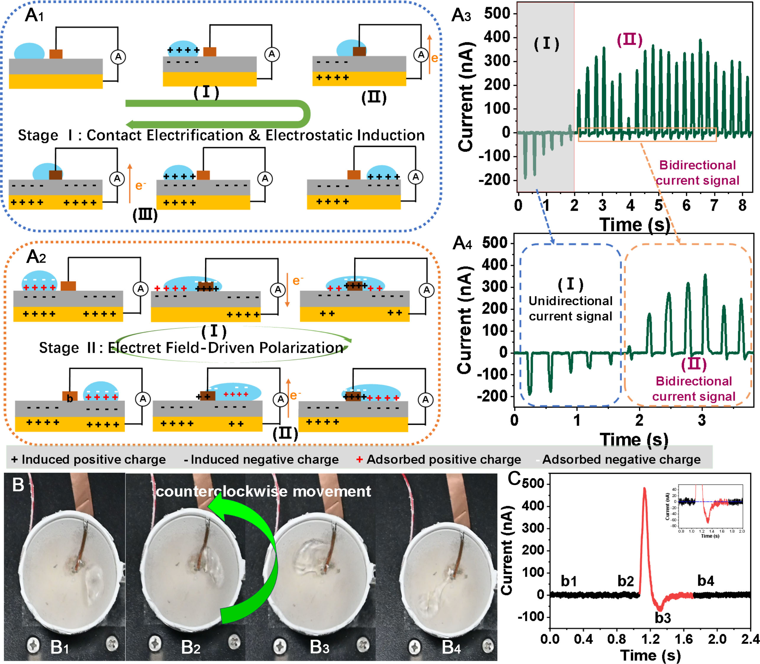
Figure 4. The evolution of the energy harvesting mechanism in the H-TENG. (A1 and A2) Schematic diagrams and corresponding electric potential/field distributions illustrating the two operational phases: (A1) The initial contact electrification phase, where charge transfer occurs upon physical contact between the droplet and the friction layer. (A2) The mature electret-driven polarization phase, where the persistent electric field from the charged friction layer polarizes the droplet (A3 and A4); (B and C) High-speed imaging and corresponding current output capture droplet-electrode interaction dynamics and transient current signatures. H-TENG: Hemispherical triboelectric nanogenerator.
As the droplet approaches the top Cu electrode, its positive charge induces negative charge on the Cu electrode surface via electrostatic induction. Upon physical contact, electrons flow from the bottom Ag electrode through the external circuit to the Cu electrode [Figure 4A1(II)], neutralizing part of the positive charge on the droplet and generating a transient positive current signal (see the shaded region in Figure 4A3). The repetitive motion of the droplet and its periodic contact with the electrode produce a series of unidirectional current signals [Figure 4A4(I)]. The current amplitude is primarily determined by three factors: the net charge carried by the droplet, its instantaneous velocity at the moment of contact, and the impedance of the external circuit. With repeated friction, negative charge gradually accumulates on the surface of the triboelectric layer [Figure 4A1(III)]. Owing to the insulating nature of the material, these surface charges exhibit slow dissipation kinetics, eventually forming an electret structure with a strong vertical electric field[22]. Once the system reaches this charge-saturation state, the power generation mechanism shifts to one dominated by the electret-field-driven polarized charge pump effect [Figure 4A2][23]. In this stage, the water droplet becomes polarized under the strong electric field: the side closer to the friction layer carries induced positive charge, while the opposite side carries negative charge [Figure 4A2(I)][24]. The contact between the polarized droplet and the Cu electrode enables rapid charge neutralization, thereby producing a large instantaneous current, with a density reaching up to 400 nA [see (II) in Figure 4A3 and A4]. As the trailing part of the droplet begins to detach from the Cu electrode [Figure 4A2(II)], residual positive charge on the electrode surface attracts electrons from the bottom Ag electrode to the top Cu electrode, resulting in a small reverse current signal [highlighted by the yellow box in (II) of Figure 4A3].
In addition to the aforementioned two-electrode wiring configuration, the H-TENG can also operate in other modes [Supplementary Figure 3A and B]. Under the single-electrode connection mode, the device outputs a dual-pulse current signal synchronized with droplet motion [Supplementary Figure 3C]. However, in this mode, the negative charges on the triboelectric layer are progressively neutralized by counter charges from the droplet during movement, thereby preventing the accumulation of charges to achieve high charge density. Consequently, sustained energy output based on the electret field-driven polarization mechanism cannot be realized. Figure 4B presents a sequential high-speed photographic series that meticulously documents the complete kinematic process of a water droplet moving within the hemispherical confinement of the H-TENG device. The image sequence captures the droplet’s dynamic interactions with the surface-mounted Cu electrode through four distinct operational phases: initial non-contact state [Figure 4B1], moment of initial contact [Figure 4B2], incipient detachment [Figure 4B3], and complete separation [Figure 4B4]. These visual observations are quantitatively correlated with the simultaneous electrical measurements presented in Figure 4C. The corresponding current output profile reveals four characteristic regimes that precisely synchronize with the visualized mechanical actions. During the non-contact phase (corresponding to Figure 4B1), the absence of physical interaction results in no measurable current signal. The moment of initial contact [Figure 4B2] triggers a substantial positive current signal with amplitude reaching approximately 500 nA, generated through immediate charge transfer via the external circuit [Figure 4C(b2)]. As the droplet begins to detach [Figure 4B3], the evolving interface geometry induces a small reverse current signal of about 50 nA, resulting from compensatory charge redistribution. Finally, upon complete detachment [Figure 4B4], the current returns to baseline as the electrical circuit is opened. This synchronized electro-mechanical analysis provides crucial evidence supporting the transition in the operational mechanism from initial contact electrification to sustained electret-field-driven polarization. The distinct dual-pulse signature - particularly the reverse current component - serves as a characteristic fingerprint of the mature operational phase where the permanently charged triboelectric layer acts as an electret, enabling continuous energy harvesting without requiring direct physical contact for each energy generation cycle. In summary, the power generation mechanism of the H-TENG evolves dynamically during operation: the initial stage relies mainly on contact electrification and electrostatic induction, producing unidirectional current signals whose magnitude correlates with contact area and motion frequency. After triboelectric charge saturation is reached, the mechanism transitions to an electret-field-driven polarized charge pump, yielding a characteristic dual-pulse current output that significantly enhances performance.
To systematically validate the operational mechanism of continuous current output via electret-field-driven polarization, this study employed the electrical double-layer (EDL) capacitance theory to quantitatively verify the proposed mechanism by analyzing the electret-field-driven droplet polarization process. Based on the electret field-driven polarized charge pump mechanism discussed above, Figure 5A and B demonstrate that for acidic solutions of different pH values, the current output of the H-TENG device decreases as the pH increases. This is primarily because, in acidic solutions, the pH value affects the ion concentration in the solution, particularly the concentration of hydrogen ions (H+). A decrease in pH (increased acidity) elevates the H+ concentration. This higher ionic strength promotes the formation of an EDL (as illustrated in Figure 5A) with higher charge density at the droplet-triboelectric layer interface during contact. Specifically, the adsorption of H+ ions onto the triboelectric layer leaves an excess of chloride counterions in the droplet, enhancing its net negative charge (electronegativity). When the droplet contacts the top electrode, this leads to an increased output, thereby improving the device’s performance. Consequently, the current output density increases as the pH decreases (as shown in Figure 5B). Similarly, when the solution becomes alkaline with a further increase in pH, positively charged sodium ions in the sodium hydroxide solution are adsorbed onto the surface of the triboelectric layer, producing a phenomenon analogous to that observed in acidic solutions, as shown in Figure 5C. Thus, the device’s output increases with rising pH, as depicted in Figure 5D. The underlying mechanism for these observations is that increased ion concentration enhances the polarization effect at the droplet-friction layer interface. The key mechanism is that an increase in ion concentration (regardless of acidity or alkalinity) compresses the thickness of the electrical double layer (EDL) (with a decrease in Debye length)[25], improves capacitance and charge transfer efficiency, and further enhances the current output of the device[26].
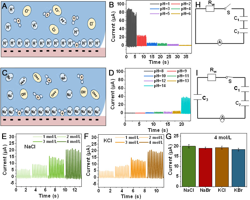
Figure 5. Mechanism of the electrical double layer (EDL) and ion concentration effects. The mechanism schematic (A) and current output (B) of acidic solutions at different pH values; The mechanism schematic (C) and current output (D) of alkaline solutions at different pH values; (E and F) respectively show the current output magnitudes of NaCl and KCl solutions at different molar concentrations; (G) illustrates the current output magnitudes of 4 M NaCl, NaBr, KCl, and KBr solutions in the form of a bar chart. Error bars represent SD. Three independent replicate experiments were performed for each condition (n = 3); (H and I) The equivalent circuit schematics. SD: Standard deviation.
To further verify the effect of positive ion concentration on the output of the H-TENG device, experiments were conducted using salt solutions of different concentrations. Figure 5E shows that as the concentration of the NaCl solution increases from 1 M to 4 M, the current output increases from 5 nA to 20 nA. A similar trend is observed for KCl solutions, as shown in Figure 5F. Finally, experiments were carried out using four different solutions - NaCl, NaBr, KCl, and KBr - all yielding similar results, as presented in Figure 5G and Supplementary Figure 4. The experimental results indicate that the output performance of the device improves with increasing positive ion concentration. This is consistent with the earlier explanation that higher ion concentrations lead to the formation of an EDL with higher charge density at the droplet-triboelectric layer interface, ultimately enhancing the device’s output performance[25]. To evaluate its stability in corrosive environments, the thin-film sample was immersed in 3.5% NaCl solution for 14 days. As shown in Supplementary Figure 4F, the post-immersion surface morphology retained good integrity compared to the original state, indicating excellent salt spray (corrosion) resistance.
Figure 5H-I provide a detailed explanation of the H-TENG’s operational mechanism using a capacitive model [27]. The system is modeled using three capacitors (Figure 5H-I). Capacitor C1 represents the dielectric [P(VDF-HFP)] between the bottom Ag electrode and the droplet, with its capacitance determined by C1 = ε0εrS/d, where S is the large effective area of the electrode and d is the film thickness. The EDL formed between the droplet and the P(VDF-HFP) surface acts as another capacitor, C2, with a smaller capacitance because the effective plate area (the droplet contact area) is much smaller than that of C1. When the droplet comes into contact with the top Cu electrode, a new EDL capacitor, C3, is formed. The water droplet itself can be considered as a resistor, Rw. A switch, S, simulates the contact (closed) and separation (open) between the droplet and the top electrode[27]. When the droplet moves without contacting the top electrode (S open), the device is in standby mode. At this stage, both capacitors C2 and C1 store charge, but the charge stored in C1 is greater than that in C2. When the droplet moves and contacts the top electrode (S closed), C3 is incorporated into the circuit. The charge stored in C1 rapidly charges C3, generating an external current (positive pulse). As the droplet detaches from the top electrode, C3 is removed from the circuit. The charge originally stored in C3 discharges back into C1, resulting in a reverse current signal in the external circuit. This model successfully simplifies the complex liquid-solid-solid three-phase interfacial interactions into a clear capacitive charging-discharging circuit, perfectly explaining the origin of the dual-pulse (Stage II in Figure 4A3) current signals observed experimentally. The introduction of the EDL capacitance concept and the equivalent circuit model thus provides a quantitative and computable theoretical framework that successfully explains the operational mechanism of the H-TENG device.
Figure 6 provides a comprehensive analysis of key factors influencing the output performance of the H-TENG, combining experimental measurements with theoretical simulations to optimize device design and operational parameters. Figure 6A presents the output performance of devices assembled with electrospun fiber mats prepared from solutions with different solid content (ranging from 8% to 18%). The results demonstrate a clear correlation between polymer concentration and electrical output. Mats spun from lower solid content solutions (8%-10%) typically exhibit finer fibers and a higher density of microspheres, which increases the specific surface area and promotes enhanced charge generation through more efficient contact electrification [Figure 2]. In contrast, higher solid content solutions produce fibers with larger and fewer spherical particles. This morphological transition reduces the overall active surface area but improves mechanical durability [Figure 3B]. This trade-off between morphological characteristics directly influences the triboelectric output, underscoring the importance of optimizing solid content to balance high surface area and structural integrity. Figure 6B examines the effect of water droplet size on output performance. Larger droplets generally produce higher current output due to their greater contact area with the triboelectric layer and increased charge carrying capacity[12]. However, beyond an optimal size, the increase in output tends to plateau, limited by the device’s charge saturation capacity and the dynamics of droplet motion within the hemispherical cavity. Figure 6C provides a schematic diagram illustrating the microscopic contact between the porous fibrous triboelectric material layer and a water droplet. The image emphasizes the role of the hierarchical micro-nano structure - composed of interwoven nanofibers and embedded spherical particles - in creating a superhydrophobic surface. This structure traps air pockets, which minimizes the actual solid-liquid contact area (reducing adhesion) and facilitates droplet rolling. The reduced adhesion and easier motion enhance charge separation and transfer efficiency during the contact-separation process[28].
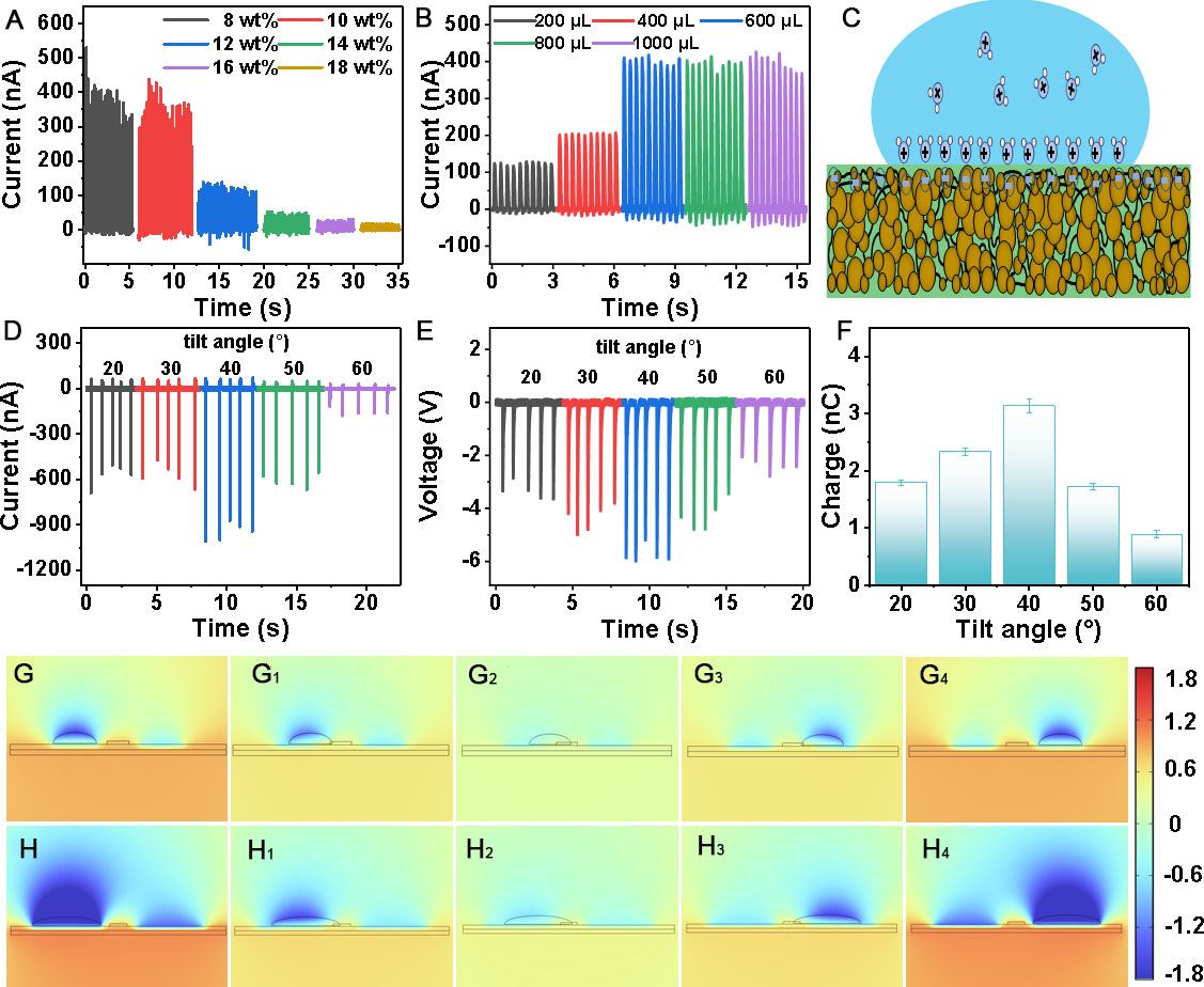
Figure 6. (A) Output performance of devices assembled with spun fiber mats obtained from solutions with different solid content; (B) Effect of water droplet size on the output of the H-TENG device; (C) Schematic diagram of the microscopic contact between the porous fibrous triboelectric material layer and a water droplet. Effect of the tilt angle between the motion height of the water droplet at different dimensional positions and the spherical bottom on the output performance of the H-TENG device: current (D), voltage (E), and charge (F), with error bars in (F) representing the standard deviation (SD), and three independent replicate experiments were performed for each condition (n = 3); Results from Finite Element Method (FEM) simulations investigating the influence of key parameters on the performance of the H-TENG: (G and H) Electric field distribution and induced charge density of water droplets with different sizes. Evolution of electric potential distribution of smaller (G-G4) and larger (H-H4) water droplets during their movement. H-TENG: Hemispherical triboelectric nanogenerator.
Figure 6D-F systematically investigate the influence of the tilt angle (relative to the spherical base) on the current output, voltage, and charge of the H-TENG, by studying the motion of droplets at different height positions along the hemispherical inner wall. The results indicate that the output is highly sensitive to the droplet’s trajectory and contact geometry. As the tilt angle of the droplet’s motion increases, the dimensionality of its movement along the inner wall of the hemisphere also increases. The optimal angle maximizes both the contact time with the electrodes and the contact area with the triboelectric layer during motion, leading to peak electrical output. The results indicate that the output of the H-TENG reaches its maximum at a tilt angle of 40 degrees [Figure 6D-F], which is the angle between the horizontal plane and the position of the droplet on the inner spherical wall. This finding is crucial for designing the curvature of the hemispherical structure and predicting its performance under actual wave-induced motion. Figure 6G and H present results from Finite Element Method (FEM) simulations based on the electret field-driven polarized charge pump mechanism, analyzing the electric field distribution and induced charge density for water droplets of different sizes. Figure 6G-G4 track the evolution of the electric potential distribution for a smaller droplet during its motion, revealing a lower potential difference due to its compact size resulting in a smaller contact friction surface area. In contrast, Figure 6H-H4 simulate a larger droplet, demonstrating a higher electric potential distribution and greater overall charge displacement. These simulations validate the experimental observations and provide a theoretical foundation for understanding how droplet size and kinematic conditions influence the electret field-driven polarization mechanism and the subsequent power generation process. Collectively, Figure 6 integrates material properties, device geometry, droplet dynamics, and theoretical modeling, collectively offering valuable guidance for optimizing the H-TENG’s efficiency in harvesting energy from water droplets across various operational conditions.
Figure 7 systematically investigates the influence of the number of top Cu electrodes and the frequency of water droplet movement on the output performance characteristics of the H-TENG. This study is crucial for optimizing device design and operational parameters to maximize energy harvesting efficiency, particularly in the context of scalable applications such as blue energy harvesting from ocean waves[29]. Figure 7A first presents a photograph of an H-TENG device with a single top Cu electrode, followed by a series of current output measurements for devices with one, two, and three Cu electrodes at different oscillation frequencies (2 Hz, 3 Hz, and 4 Hz). The corresponding current signals for each electrode configuration and frequency are shown in Figure 7B-D. Furthermore, Figure 7A1-A3 provide a comparative summary of the current output across different numbers of electrodes and frequencies, clearly illustrating the performance trends.

Figure 7. Systematic study of the effect of the number of top Cu electrodes and the frequency of water droplet movement on the output characteristics of the H-TENG device: (A) Photograph of an H-TENG device with one top Cu electrode; (B-D) Corresponding current signals of H-TENGs with different numbers of top Cu electrodes (1, 2, and 3 Cu electrodes) at 2 Hz, 3 Hz, and 4 Hz, respectively. (A1, A2, A3) Comparison of current output data of H-TENG devices with 1, 2, and 3 Cu electrodes at different frequencies. Corresponding current signals obtained with a single Cu electrode assembled H-TENG at 2 Hz (B1), 3 Hz (C1), and 4 Hz (D1). Corresponding current signals obtained with a two Cu electrode assembled H-TENG at 2 Hz (B2), 3 Hz (C2), and 4 Hz (D2). Corresponding current signals obtained with a three Cu electrode assembled H-TENG at 2 Hz (B3), 3 Hz (C3), and 4 Hz (D3). H-TENG: Hemispherical triboelectric nanogenerator.
The results demonstrate that increasing the number of top electrodes enhances the current output [Figure 7A1-A3]. This is because multiple electrodes provide more opportunities for the moving droplet to make contact, thereby increasing the frequency of charge transfer events per oscillation cycle. Each contact event triggers electron flow between the bottom and top electrodes via the external circuit, contributing to a higher cumulative current[30]. However, this enhancement exhibits diminishing returns due to factors such as overlapping contact zones and limited charge replenishment rates (as shown in Figure 7B-D)[31]. Moreover, increasing the oscillation frequency of the droplet also boosts the current output. Higher frequencies lead to more contact events per unit time, which directly increases the current output, as current is defined as charge transferred per unit time[32]. The data show that at 4 Hz, the current output is significantly higher than at 2 Hz for all electrode configurations [Figure 7A1-A3]. This frequency-dependent behavior underscores the importance of kinematic conditions in real-world applications, such as wave-driven energy harvesting, where motion frequency can vary.
Notably, the combination of multiple electrodes and higher frequencies yields the best performance. For instance, as shown in Figure 7A1-A3, a device with three Cu electrodes operating at 4 Hz yields maximized charge output. This synergistic effect highlights the potential for optimizing H-TENG arrays by tuning both structural and kinematic parameters. The underlying mechanism remains consistent with the electret-field-driven polarization model described earlier. Once the triboelectric layer reaches charge saturation, the persistent electric field polarizes the droplet, enhancing charge separation and enabling efficient energy generation even without continuous physical friction. The multi-electrode design leverages this mechanism by providing multiple discharge contact points for the polarized droplet, thereby amplifying the output. Additionally, the H-TENG device stability and the effect of different wave amplitudes on the device current output are shown in Supplementary Figure 5A and B, respectively. Supplementary Figure 5C demonstrates robust charge retention, with the surface potential retaining 82.8% of its initial value after 8 hours in a 95% relative humidity environment. The results indicate that the device has good wear resistance and stable output, and that the device output is positively correlated with the wave amplitude. The results indicate a positive correlation between wave size and device output. Finally, the current and corresponding peak power density data of the device under different external load resistances are presented in Supplementary Figure 5D. In summary, Figure 7 provides essential experimental insights into how electrode multiplicity and motion frequency can be harnessed to enhance the performance of the H-TENG. These findings provide direct guidance for the design of large-scale arrays for ocean wave energy harvesting, where optimizing the number of contact points and adapting to natural wave frequencies are key to achieving continuous and scalable power generation.
CONCLUSIONS
In summary, we have developed a H-TENG with an innovative dual-electrode architecture that significantly advances droplet-based energy harvesting. The device operates through a transformative two-stage mechanism - beginning with conventional contact electrification and evolving into sustained electret-field-driven polarization - enabling continuous energy generation with minimal reliance on direct physical contact. This overcomes the fundamental limitation of intermittency in conventional TENGs. The hemispherical design permits a single droplet to undergo sustained energy conversion cycles under wave-like motion, making it exceptionally suitable for scalable blue energy harvesting from ocean waves. Systematic experimental and theoretical analyses demonstrate the critical roles of droplet dynamics, ion concentration, and device geometry in enhancing performance. By integrating material innovation with optimized structural design, this work establishes an efficient, durable, and sustainable strategy for powering distributed electronics and marine sensors, marking a substantial step toward practical applications in self-powered systems and large-scale renewable energy harvesting.
DECLARATIONS
Acknowledgements
The authors are grateful to Prof. Bingpu Zhou from University of Macau for his valuable assistance and unwavering support in our research using Comsol Multiphysics software.
Authors’s contributions
Conceptualization, investigation, writing - original draft: Chang, C.
Investigation, methodology: Lan, S.; Gao, D.
Methodology: Xie, J.
Supervision, writing-review & editing, funding acquisition: Mao, Y.
Supervision, writing-review & editing: Hu, W.
Availability of data and materials
The data that support the findings of this study are available from the corresponding authors upon reasonable request.
AI and AI-assisted tools statement
During the preparation of this manuscript, the AI tool DeepSeek (version V2.5, released 2024-09-05) was used solely for language editing. The tool did not influence the study design, data collection, analysis, interpretation, or the scientific content of the work. All authors take full responsibility for the accuracy, integrity, and final content of the manuscript.
Financial support and sponsorship
This work was supported by the National Natural Science Foundation of China (Grant Nos. 22269025 and 22175150), and Yunnan Fundamental Research Projects (Grant No. 202301AT070210).
Conflicts of interest
All authors declared that there are no conflicts of interest.
Ethical approval and consent to participate
Not applicable.
Consent for publication
Not applicable.
Copyright
© The Author(s) 2026.
Supplementary Materials
REFERENCES
1. Wang, H.; Yin, Y.; Su, Z.; et al. Bio‐based and recyclable self‐healing elastomer for the application of self‐powered triboelectric nanogenerator in low‐temperature. Adv. Funct. Mater. 2023, 34, 2311649.
2. He, X.; Zi, Y.; Guo, H.; et al. A highly stretchable fiber‐based triboelectric nanogenerator for self‐powered wearable electronics. Adv. Funct. Mater. 2016, 27, 1604378.
3. Lee, J. H.; Kim, S.; Kim, T. Y.; Khan, U.; Kim, S. Water droplet-driven triboelectric nanogenerator with superhydrophobic surfaces. Nano Energy 2019, 58, 579-84.
4. Xu, W.; Zheng, H.; Liu, Y.; et al. A droplet-based electricity generator with high instantaneous power density. Nature 2020, 578, 392-6.
5. Hu, C.; Wang, W.; Liu, Y.; et al. High-output solid liquid triboelectric nanogenerator enhanced by the regulation of interfacial wettability. Nano Energy 2024, 130, 110132.
6. Lin, Z. H.; Cheng, G.; Lee, S.; Pradel, K. C.; Wang, Z. L. Harvesting water drop energy by a sequential contact-electrification and electrostatic-induction process. Adv. Mater. 2014, 26, 4690-6.
7. Lai, Y. C.; Ginnaram, S.; Lin, S. P.; Hsu, F. C.; Lu, T. C.; Lu, M. H. Breathable and stretchable multifunctional triboelectric liquid‐metal e‐skin for recovering electromagnetic pollution, extracting biomechanical energy, and as whole‐body epidermal self‐powered sensors. Adv. Funct. Mater. 2023, 34, 2312443.
8. Shuvo, A. A.; Bhuiyan, A. G.; Islam, M. S. Finite element modeling of MXene/PVDF-based high-performance triboelectric nanogenerators for self-powered wearable electronics. ACS Appl. Electron. Mater. 2024, 6, 4478-88.
9. Xi, Y.; Guo, H.; Zi, Y.; et al. Multifunctional TENG for blue energy scavenging and self‐powered wind‐speed sensor. Adv. Energy Mate. 2017, 7, 1602397.
10. Shao, H.; Cheng, P.; Chen, R.; et al. Triboelectric-electromagnetic hybrid generator for harvesting blue energy. Nanomicro. Lett. 2018, 10, 54.
11. Jang, S.; La, M.; Cho, S.; et al. Monocharged electret based liquid-solid interacting triboelectric nanogenerator for its boosted electrical output performance. Nano Energy 2020, 70, 104541.
12. Cheon, S.; Kang, H.; Kim, H.; et al. High‐performance triboelectric nanogenerators based on electrospun polyvinylidene fluoride-silver nanowire composite nanofibers. Adv. Funct. Mater. 2017, 28, 1703778.
13. An, S.; Jo, H. S.; Li, G.; Samuel, E.; Yoon, S. S.; Yarin, A. L. Sustainable nanotextured wave energy harvester based on ferroelectric fatigue‐free and flexoelectricity‐enhanced piezoelectric P(VDF‐TrFE) nanofibers with BaSrTiO3 nanoparticles. Adv. Funct. Mater. 2020, 30, 2001150.
14. Cheng, Y.; Wang, J.; Lu, X.; Wang, C. An all-nanofibrous Janus textile with directional perspiration for triboelectric nanogenerator and self-powered e-skin sensor. Nano Energy 2023, 117, 108852.
15. Shrestha, K.; Pradhan, G. B.; Bhatta, T.; et al. Intermediate nanofibrous charge trapping layer-based wearable triboelectric self-powered sensor for human activity recognition and user identification. Nano Energy 2023, 108, 108180.
16. Stanton, M. M.; Ducker, R. E.; MacDonald, J. C.; Lambert, C. R.; McGimpsey, W. G. Super-hydrophobic, highly adhesive, polydimethylsiloxane (PDMS) surfaces. J. Colloid Interface Sci. 2012, 367, 502-8.
17. Chen, H.; Liu, Y.; Yan, M.; et al. Enhanced energy density in sandwich-structured P(VDF-HFP) nanocomposites containing Hf0.5Zr0.5O2 nanofibers. Chem. Eng. J. 2022, 436, 131123.
18. Zeng, Q.; Chen, A.; Zhang, X.; Luo, Y.; Tan, L.; Wang, X. A dual-functional triboelectric nanogenerator based on the comprehensive integration and synergetic utilization of triboelectrification, electrostatic induction, and electrostatic discharge to achieve alternating current/direct current convertible outputs. Adv. Mater. 2023, 35, e2208139.
19. Hinchet, R.; Ghaffarinejad, A.; Lu, Y.; Hasani, J. Y.; Kim, S.; Basset, P. Understanding and modeling of triboelectric-electret nanogenerator. Nano Energy 2018, 47, 401-9.
20. Feng, M.; Kong, X.; Feng, Y.; et al. A new reversible thermosensitive liquid-solid TENG based on a P(NIPAM-MMA) copolymer for triboelectricity regulation and temperature monitoring. Small 2022, 18, e2201442.
21. He, Y.; Wang, H.; Sha, Z.; Boyer, C.; Wang, C.; Zhang, J. Enhancing output performance of PVDF-HFP fiber-based nanogenerator by hybridizing silver nanowires and perovskite oxide nanocrystals. Nano Energy 2022, 98, 107343.
22. Mahanty, B.; Ghosh, S. K.; Garain, S.; Mandal, D. An effective flexible wireless energy harvester/sensor based on porous electret piezoelectric polymer. Mater. Chem. Phys. 2017, 186, 327-32.
23. Kim, J.; Han, G. H.; Kim, S.; et al. Electric-field-driven interfacial trapping of drifting triboelectric charges via contact electrification. Energy Environ. Sci. 2023, 16, 598-609.
24. Chun, J.; Ye, B. U.; Lee, J. W.; et al. Boosted output performance of triboelectric nanogenerator via electric double layer effect. Nat. Commun. 2016, 7, 12985.
25. Tadmor, R.; Hernández-zapata, E.; Chen, N.; Pincus, P.; Israelachvili, J. N. Debye length and double-layer forces in polyelectrolyte solutions. Macromolecules 2002, 35, 2380-8.
26. Wu, J. Understanding the electric double-layer structure, capacitance, and charging dynamics. Chem. Rev. 2022, 122, 10821-59.
27. Zhang, Q.; Li, Y.; Cai, H.; et al. A single-droplet electricity generator achieves an ultrahigh output over 100 V without pre-charging. Adv. Mater. 2021, 33, e2105761.
28. Li, Z.; Zhu, M.; Qiu, Q.; Yu, J.; Ding, B. Multilayered fiber-based triboelectric nanogenerator with high performance for biomechanical energy harvesting. Nano Energy 2018, 53, 726-33.
29. Zhang, D.; Shi, J.; Si, Y.; Li, T. Multi-grating triboelectric nanogenerator for harvesting low-frequency ocean wave energy. Nano Energy 2019, 61, 132-40.
30. Xu, S.; Ding, W.; Guo, H.; Wang, X.; Wang, Z. L. Boost the performance of triboelectric nanogenerators through circuit oscillation. Adv Energy Mater 2019, 9, 1900772.
31. Lei, R.; Shi, Y.; Ding, Y.; et al. Sustainable high-voltage source based on triboelectric nanogenerator with a charge accumulation strategy. Energy Environ. Sci. 2020, 13, 2178-90.
Cite This Article
How to Cite
Download Citation
Export Citation File:
Type of Import
Tips on Downloading Citation
Citation Manager File Format
Type of Import
Direct Import: When the Direct Import option is selected (the default state), a dialogue box will give you the option to Save or Open the downloaded citation data. Choosing Open will either launch your citation manager or give you a choice of applications with which to use the metadata. The Save option saves the file locally for later use.
Indirect Import: When the Indirect Import option is selected, the metadata is displayed and may be copied and pasted as needed.
About This Article
Special Topic
Copyright

Data & Comments
Data
0


Comments
Comments must be written in English. Spam, offensive content, impersonation, and private information will not be permitted. If any comment is reported and identified as inappropriate content by OAE staff, the comment will be removed without notice. If you have any queries or need any help, please contact us at [email protected].