


Photovoltaic plant losses: spectral mismatch
 0
0 Abstract
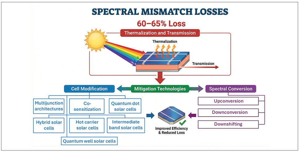
Understanding solar photovoltaic plant losses, including optical and electrical losses, is vital to developing mitigating strategies and ensuring the economic viability of solar projects. The most significant optical loss is spectral mismatch. Spectral mismatch losses include thermalization and transmission. Spectral mismatch accounts for approximately 60% to 65% of total energy losses in conventional solar panels, with thermalization constituting around 2/3 and transmission representing the remaining. This paper shares the essential fundamentals underlying spectral mismatch, quantitatively reports spectral mismatch losses for various conditions, and discusses the mitigating strategies and their potential effectiveness. An intercomparison of the reviewed mitigation technologies is provided for PV stakeholders and researchers, comparing commercial readiness, cost, manufacturability, and efficiency improvement potential. Mitigation technologies include cell modification and spectral conversion, both of which are discussed in detail, including multijunction structures, co-sensitization, hot carrier and hybrid thermoelectric solar cells, quantum dot and quantum well solar cells, upconversion, downconversion, and downshifting.
Keywords
INTRODUCTION
In the realm of renewable energy, solar power stands out as one of the pivotal solutions in the quest for sustainable and eco-friendly electricity generation[1, 2]. The deployment of solar photovoltaic (PV) plants has witnessed a remarkable surge in recent years[3], aiming to reduce greenhouse gas emissions and mitigate the impacts of climate change[4]. To put this into perspective, solar PV generation increased by 270 terawatt hours (TWh) in 2022, marking a 26% rise compared to 2021[5]. PV technology constitutes 4.5% of the overall global electricity production, maintaining the position of solar energy as the third most prominent renewable electricity source after hydropower and wind energy[6]. However, despite the numerous advantages of PV technology, the efficiency and energy density of solar power generation are challenged by various energy conversion losses that affect the economic viability of solar installations. Suboptimal energy conversion efficiency reduces revenue generation and extends payback periods.
PV losses are generally categorized as either optical or electric losses. Optical losses include shading, spectral mismatch, reflection, transmission, and parasitic losses, while electric losses include bulk recombination, surface recombination, and bandgap. The most predominant among these losses is spectral mismatch, which significantly limits the efficiency of modern PV cells by contributing to an extensive amount of roughly 65% of the total energy losses in single junction solar cells. Spectral mismatch losses result from internal physical limitations within the absorber material caused by energy discrepancies between the majority of the photons incident in the sunlight spectrum and the absorber's bandgap. Specifically, spectral mismatch encompasses two subcategories: transmission and thermalization. Transmission losses occur when the energy of an incident photon is below that of the solar cell's bandgap and therefore cannot be absorbed[7]. On the contrary, thermalization losses occur when photons are absorbed which possess surplus energy beyond the cell's bandgap. The excess energy beyond the bandgap energy dissipates as heat and is therefore wasted[8].
Individual technologies for the mitigation of spectral mismatch losses have previously been reviewed in the literature. However, these reviews largely center on the scientific progress made in individual mitigation technologies, rather than providing a holistic and comparative assessment of the most promising spectral mismatch mitigation methods. Examples of such technology-specific review papers include a review on downconversion/downshifting (DC/DS) based silicate phosphors aiming to mitigate spectral mismatch[9], a review covering recent advances in wide-bandgap multijunction (MJ) solar cells[10], or a review on tunable bandgap perovskite solar cells (PSCs) as spectral mismatch mitigators[11].
It follows that such presently available reviews cannot offer PV stakeholders an easily accessible intercomparison and critical analysis of different, promising spectral mismatch mitigation methods. The present review aims to address this gap by first exploring the root causes of spectral mismatch and then holistically reviewing the most promising spectral mismatch mitigation technologies. Explanations of the physical working principles of each technology are provided, highlighting timely experimental or numerical results obtained for each method with particular focus on power conversion efficiency (PCE). A critical assessment of the current viability of each technology follows via an intercomparison revolving around cost-scalability, technological maturity, near-future potential, and integration challenges.
In doing so, actionable insights are created, which are of high value for stakeholders in the PV industry such as investors, policymakers, and project developers. The presented insights serve as guidelines for making informed decisions and effectively allocating resources for the design, implementation, and operation of solar installations with optimal efficiency.
For a better overview, the discussed mitigation technologies are divided into two categories: cell modification and spectral conversion. The first of the discussed categories, cell modification, describes the mitigation approach in which the cell architecture itself is developed. The most promising technological approaches in this category covered in this paper are MJ solar cells, co-sensitization of dye-sensitized solar cells (DSSCs), hot carrier solar cells (HCSCs), hybrid solar cells, and intermediate band solar cells (IBSCs). The second approach, spectral conversion, revolves around the modification of the incident solar spectrum so that a better match with the PV cell's absorption characteristics is achieved. The most promising spectral conversion techniques include upconversion (UC), DC, and DS, each of which are covered in this review.
SPECTRAL MISMATCH
Spectral mismatch describes the mismatch between the photon energy associated with different wavelengths across the incident solar spectrum and the cell's bandgap energy. This bandgap needs to be overcome to transfer an electron from the valence band to the conduction band of the cell[12]. Thus, variations in the incident solar spectrum and its average photon energy affect spectral mismatch[13].
The solar spectrum ranges from a wavelength of ~250 nm to ~3,000 nm, comprised of ultraviolet (UV) light in the range of ~250 nm to ~380 nm, visible light in the range of ~380 nm to ~740 nm, and infrared light in the range of ~740 nm to ~2,500 nm[14]. The spectral distribution of solar radiation can be seen in Figure 1. Meanwhile, crystalline silicon (c-Si) solar cells can "efficiently" generate electrical energy in the range of 300 nm to 1,160 nm[15]. This excludes most of the wavelengths in the UV range as photons associated with wavelengths less than 300-400 nm are absorbed very close to the surface of the cell, where many carriers recombine before contributing to current, due to a high density of defects, dangling bonds, and surface states. Similarly, a large portion of the infrared spectrum is excluded, as silicon's absorption cut-off at approximately 1,160 nm corresponds to its bandgap energy of 1.12 eV.
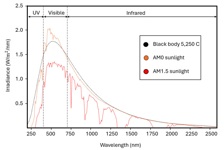
Figure 1. Spectral distribution (irradiance vs. wavelength) of black body radiation at 5,250 °C, AM0 sunlight, and AM1.5 sunlight.
The maximum PCE achieved by various kinds of solar cells is predominantly governed by losses due to spectral mismatch[16]. To put the significance of spectral mismatch into perspective, it makes up 65% of the total energy loss for single junction, conventional silicon solar cells (SSCs)[17]. Thus, finding and improving ways to harness this unused energy within the incident irradiance proves critical in increasing PV efficiency and in enabling a green energy future. Spectral mismatch results in energy losses through two different mechanisms (see Figure 2)[17]:
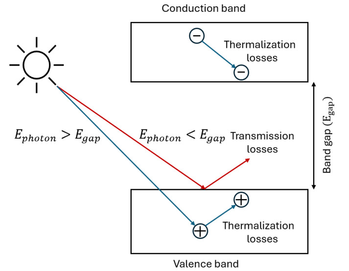
Figure 2. Visualization of thermalization (blue arrows) and sub-bandgap transmission (red arrows) as the two major spectral mismatch loss mechanisms.
Transmission: When the energy of an incident photon is smaller than the cell's bandgap energy, the photon cannot be absorbed and, therefore, does not contribute to the device's photocurrent. The photon energy remains unused. Photon transmission accounts for about 20% of the energy lost from incident irradiance[18].
Thermalization: When the energy of an absorbed photon exceeds the bandgap energy and an electron has excess energy after excitation, during the relaxation of this hot carrier, the surplus energy dissipates into heat. Without harvesting energy past the bandgap, even high-energy blue photons produce the same outcome as lower-energy red photons[19]. Even in highly efficient PV devices, at least 40% of the available power is lost due to heat dissipation caused by hot carrier thermalization[20].
The theoretically achievable limiting efficiency of solar cells is commonly expressed by the Shockley-Queisser limit[21]. Assumptions made in the calculation of the Shockley-Queisser limit include absorption of photons only above the bandgap energy, thermalization of the excess energy of above-bandgap photons, illumination of the solar cell with unconcentrated sunlight, and an external quantum efficiency (EQE) equal to one, meaning one electron-hole pair per absorbed photon. For example, the theoretical limiting efficiency as expressed by the Shockley-Queisser limit for single junction solar cells under unconcentrated AM1.5 irradiance ranges between 32% for SSCs, which have a bandgap of 1.12 eV, and 33.7% for absorbers with an ideal 1.34 eV bandgap.
Allowing for graphical interpretation, the detailed balance model makes sub-bandgap transmission losses, thermalization losses, and radiative losses for different bandgaps under AM1.5 irradiance more accessible[22]. Under ideal conditions,
The impact of spectral mismatch varies with changes to the incident spectrum. These changes can be due to fluctuations in the atmosphere surrounding the solar cell over the course of a day, season, and year. Therefore, prior to introducing techniques to mitigate spectral mismatch losses, an understanding of certain spectrum-influencing atmospheric parameters and concepts is crucial, including air mass (AM), atmospheric aerosol contents, precipitable water content in the atmosphere, and atmospheric ozone levels.
Air mass measures how much air the sunlight must travel through before reaching the ground. It is expressed through the air mass coefficient, which measures the actual path length sunlight travels through the atmosphere relative to the shortest path length (when the sun is directly overhead). The air mass coefficient changes with the diurnal and seasonal changes in the sun's path. Higher air mass, which results in increased absorption and scattering of incoming sunlight, decreases light intensity and affects the spectral composition of the light incident on a given solar cell. Sunlight with an altered spectral composition might then be converted into electricity less efficiently, decreasing overall solar cell performance. Additionally, such scattering and absorption of sunlight in the atmosphere are driven by both aerosols and precipitable water vapor. Aerosols are small, solid particles suspended in the atmosphere. Despite their low atmospheric concentration, aerosols significantly influence the optical characteristics of light in the visible range of the solar spectrum. Precipitable water vapor, on the other hand, amplifies the absorption of light in the infrared range of the solar spectrum, particularly affecting the performance of solar cells optimized towards infrared wavelengths. In zones of higher barometric pressures, where the density of water vapor in the atmosphere is increased, the effects of water vapor on solar cell performance may be further amplified. Conversely, ozone strongly absorbs UV light, indirectly shifting the spectral balance towards visible and infrared wavelengths. This effect can even benefit the performance of PV cells, such as c-Si cells, which are not optimized to utilize UV wavelengths efficiently. It follows from the above-mentioned influences of atmospheric parameters on the performance of a solar cell that increasing a solar cell's spectral robustness proves critical in mitigating the effects of spectral mismatch under real-world conditions.
Spectral mismatch during the testing stage
Due to these real-world spectral variations, spectral mismatch also poses a challenge in the testing stage of solar cells. Solar simulators such as xenon arc lamps or LED light arrays with spectral filters generate reference spectra such as the AM1.5 spectrum[24]. Before using solar simulators, the generated simulator spectra are typically calibrated by using a reference solar cell. Under a given reference spectrum and standard test conditions, a reference cell has a known spectral response and produces a known Ⅳ curve. A simulator spectrum may then be considered calibrated when e.g. the short circuit current produced by the irradiated reference cell approaches the expected value under the reference spectrum. The test cell is placed under this calibrated simulator spectrum to evaluate its performance. Any deviation between the spectral response pattern of the test and the reference cell or any mismatch between the simulator spectrum and the reference spectrum results in errors in the cells' efficiency measurements. To correct any such errors in the measurement of the test cell's efficiency, efficiency deviations are quantified via the spectral mismatch correction factor[25]. This spectral mismatch error does not necessarily mean an overestimation of the cells' performance. In fact, changes to the composition of the incident solar spectrum across the day can be advantageous and lead to the spectrum better matching the cell's absorption profile compared to the simulator spectrum. For example, during summertime, a blueshift is observed, resulting in an increased average photon energy across the incident spectrum compared to the AM1.5G reference spectrum under standard test conditions. This leads to a spectral gain and, potentially, a better match between the incident spectral composition and the spectral absorption pattern of the solar cell. On the contrary, a redshift, meaning a decreased average photon energy across the incident spectrum, can be observed during the winter months, potentially leading to increased spectral mismatch losses due to a greater deviation between the incident spectral composition and the cell's spectral absorption pattern[13].
Spectral mismatch effects from cell to system level
Spectral mismatch impacts PV devices both on a cell-to-cell level and on a module level during integration into real-world applications. The performance of PV modules, which are commonly comprised of several PV cells connected in series, is determined by the cell producing the lowest current. Variations in the current output are largely governed by differences in spectral response caused by factors such as manufacturing inconsistencies. Previous studies have largely omitted the impact of cell-level spectral response variations on the total performance of PV modules. Recent NREL studies, however, have quantified this impact in a new approach based on the cell-level analysis of EQE variations[26]. For instance, a recent study documented cell-level EQE vs. wavelength curves of 11 individual PV modules from different manufacturers under AM1.5 irradiance at 1,000 W/m2 and 25 °C for locations across the entire USA throughout the year[26]. Variations in the PV module's energy output due to spectral mismatch as high as
A PV integration case impacted by spectral mismatch is the emerging application of building-integrated PV (BIPV) systems. In such systems, PV devices are integrated into architectural design elements of buildings such as building facades, flat or inclined roofs, or shading systems. The concept of BIPV is attractive to stakeholders because no additional space outside of the building itself is required and the dual functionality of the employed PV devices as both a power source and construction material[27]. However, due to the unique orientation, positioning along the facade, and often steep or even vertical tilt angles, PV devices in BIPV systems are exposed to unique spectral distributions potentially promoting spectral mismatch loss mechanisms. Given the growing role of BIPV systems in modern urban architecture, recent studies have presented newly developed models to characterize spectral mismatch in BIPV applications.
In one such study, a new model was developed which quantifies spectral gains and losses of vertically mounted (90°) BIPV devices based on monocrystalline/amorphous Si (m-Si/a-Si, respectively), CIGS, and CdTe solar cell technology exposed to unique spectral conditions arising from diurnal air mass variations[28]. With increasing air mass/zenithal angle, an increasing power generation deficit relative to power generation under the ASTM G173 reference spectrum was predicted for m-Si and CIGS cells (expressed by a spectral mismatch factor < 1). On the contrary, for a-Si and CdTe cells, power generation relative to reference conditions increased with increasing air mass. Notably, spectral mismatch remained near-constant across most air masses for the CdTe cell, allowing air mass to be used as a predictor for spectral mismatch with this cell type.
A similar study investigating the spectral mismatch caused by the influence of orientation on vertical c-Si BIPV modules predicts that north-facing modules experience the most pronounced monthly spectral mismatch losses (namely a spectral mismatch factor between 0.90 and 0.95)[29]. On the contrary, south facing panels produced the most favorable results on account of being the only orientation in which limited spectral gains occurred during summer (all other orientations produced spectral mismatch losses during both the winter and summer season). East and west facing modules produced comparable results with more dispersed and smoothly varying monthly spectral mismatch losses. The reported results underscore the critical importance of assessing favorable options for module orientation and tilt angle when designing BIPV systems, as well as selecting an appropriate cell technology in BIPV applications.
MITIGATION OF SPECTRAL MISMATCH LOSSES
Ongoing research aims to discover new techniques which enable PV devices to harvest a wider range of the incident solar spectrum to mitigate losses due to spectral mismatch[16]. The two main strategies for achieving this are adapting the spectrum incident on the solar cell (spectral conversion) and modifying the solar cell itself[17] to enhance absorption characteristics across a broader spectral range. Figure 3 summarizes promising spectral mismatch mitigating technologies for both methodologies.
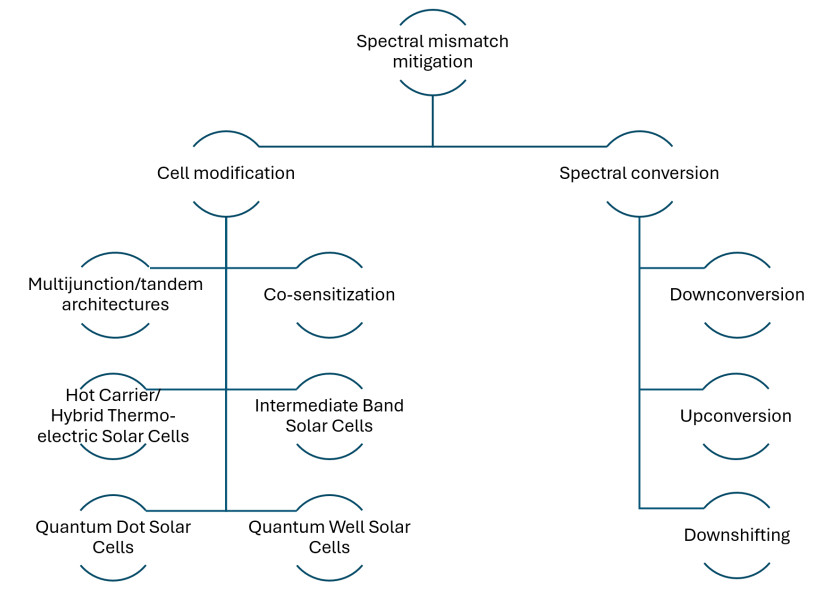
Figure 3. Technological approaches to mitigating losses due to spectral mismatch divided into cell modification and spectral conversion categories.
Cell modification
Multijunction solar cells
MJ and tandem solar cells mitigate spectral mismatch by increasing the system's absorption range and harvesting more energy from across the incident spectrum as compared to standalone solar cells. In MJ solar cells, a series of cells with optimized individual absorption ranges is combined into cell stacks. The resulting overall absorption range of the cell stack is thus widened compared to the individual absorption ranges of the subcells, as visualized in Figure 4. In these cells, spectral mismatch is therefore directly mitigated through energy harvesting of an extended range of incident photons by the respective subcell whose bandgap best matches the photon's energy. The cells can be integrated into a unified structure using either mechanical interconnection or monolithic integration approaches[16]. In organic tandem solar cells, for example, combining ITO/P3HT: PCBM/Al processed as a diffused bilayer with an absorption range between 375 and 630 nm as the bottom cell, and ITO/ZnPc/ZnPc: C60/C60/Cr/Al as the top cell with an absorption range between 600 and 800 nm. This combination increases effective total absorption range of the hybrid system to [375-800 nm][30].
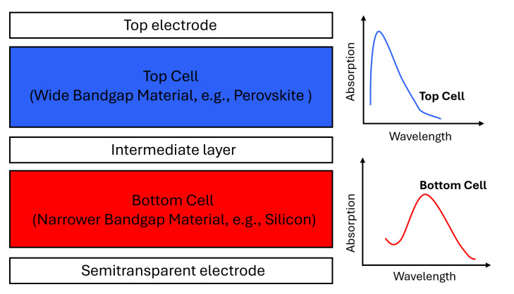
Figure 4. Layered tandem solar cell structure and the respective absorption spectra of the absorber materials. The absorber materials are combined to widen the overall absorption range and thus mitigate spectral mismatch.
Due to their better matched, broader absorption pattern, the limiting efficiency of MJ solar cells exceeds the Shockley-Queisser limit of conventional, single junction SSCs[31]. For a hypothetical MJ cell of an infinite number of cells, the maximum PCE under one sun illumination is 68.2%, and as much as 86.8% under highly concentrated sunlight[32]. In this case, spectral mismatch is reduced to a minimum as there would exist an optimized subcell for the absorption of each specific photon in the incident solar spectrum and its associated energy.
Popular cell types for integration into tandem architectures include III-V solar cells, cells with c-Si, the highly promising solid-state PSCs, and thin-film solar cells (TFSCs). III-V MJ solar cells are advanced solar cells that combine semiconductor materials from the third (III) and the fifth (V) groups of the periodic table in the form of multiple stacked layers, each optimized to absorb a specific portion of the solar spectrum.
Under unconcentrated (one sun) AM1.5G irradiance at 1,000 W/m2, a remarkable PCE of 39.2% has been achieved by a monolithically grown inverted metamorphic six-junction III-V solar cell in 2020[33], with a notable open-circuit voltage V
Silicon with a 1.1 eV bandgap is close to the optimum for dual-junction and triple-junction devices aiming to reduce spectral mismatch losses. Therefore, aiming to combine the high PCE of modern c-Si solar cells with the high potential of III-V MJ solar cells is another focus of current MJ device research. A promising attempt at manufacturing high-performance, high-reliability III-V silicon tandem solar cells at competitive costs is direct growth of III-V absorber layers using methods such as metalorganic vapor-phase epitaxy (MOVPE). This methodology utilizes a precise crystal growth technique where metal-organic and hydride gases are used to deposit thin absorber layers on a substrate[34]. However, for direct growth of III-V absorber layers onto silicon, achieving low enough defect densities proves challenging due to the large difference in the thermal expansion coefficient as well as the 3%-4% difference in the lattice constant between the III-V layers and silicon. One such triple-junction III-V silicon tandem solar cell in which III-V layers were epitaxially grown onto GaAs, featuring a top tandem wafer-bonded to a TOPCon (tunnel oxide passivated contact) silicon bottom cell, achieved a remarkable PCE of 36.1% under unconcentrated (one sun) AM1.5G irradiance[35].
PSCs, which use perovskites as light absorbers, are another popular cell type for tandem configurations. Perovskite materials consist of crystal structures with the chemical formula ABX3. Examples for perovskite materials include lead halides such as formamidinum lead iodide (CH5I3N2Pb, also denoted FAPbI3)[36] or the archetypal methylammonium lead iodide (CH3NH3PbI3, also denoted MAPbI3). However, due to concerns related to the long-term stability, as well as the toxicity of the lead[37], lead-free, all-inorganic alternatives such as the caesium antimony iodide Cs3Sb3I9[38] or caesium tin iodide Cs2SnI6[39] are gaining popularity. There exist two main PSC cell architectures. The first is a sensitized solar cell architecture with a liquid electrolyte, often referred to as a liquid-state PSC, where perovskites serve as photon-absorbing sensitizers for carrier excitation. The second, more actively studied PSC architecture, is a PV cell structure employing perovskites as solid state absorbers as visualized in Figure 5.
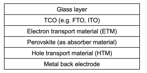
Figure 5. Schematic structure of a solid state PSC.
MJ devices based on stacked solid state perovskite absorbers represent a key focus in PV cell research. Numerical simulations investigating thickness-optimized PSC tandem devices with maximal light absorption across unconcentrated (one sun) AM1.5G irradiance have returned highly promising PCE's as high as 28.15%[40]. A recent experimental study of a monolithic perovskite-perovskite-silicon triple junction cell with optimized light management and maximized photocurrent has achieved a PCE of 24.4%[41], approaching simulated values. Beyond its high PCE, the device exhibited excellent thermal stability, retaining 96.6% of its initial PCE after exposure to a N2 atmosphere at 85 °C for around 1,000 h. See Table 1 for more details.
Electrical characterizations of several MJ/tandem PV cell technologies under unconcentrated (one sun) irradiance reported in experimental and numerical studies
| III-V MJ cells | |||||||
| Cell | Test conditions | Voc[V] | Jsc [mA/cm2] | FF [%] | PCE [%] | Year | Source |
| AlGaInP/AlGaAs/GaAs// GaInAs/GaInAs/GaInAs (6J) 350 ym finger spacing | Experimental - AM1.5G | 5.55 | 8.46 | 83.5 | 39.2 | 2020 | [33] |
| GaInP/InGaAs/Ge | Numerical simulation - AM1.5G @ 300 K | 2.93 | 11.72 | 91.58 | 31.46 | 2024 | [42] |
| GaInP/InGaAs/Ge | Numerical simulation -AM1.5 @ 298 K | 2.7 | 13.3 | 85.4 | 30.1 | 2024 | [43] |
| GaInP/GaAs/Ge w/ screen printed silver paste front electrode | Experimental - AM1.5G @ 298 K - Sun 2000 solar simulator | 2.69 | 12.25 | 86.64 | 28.56 | 2024 | [44] |
| MJ cells with Si bottom cells | |||||||
| Cell | Test conditions | Voc[V] | Jsc [mA/cm2] | FF [%] | PCE [%] | Year | Source |
| GaInP/GaInAsP//Si rear-heterojunction in middle & top cell | Experimental - AM1.5G | 3.309 | 12.7 | 86 | 36.1 | 2023 | [35] |
| GaInP/GaAs//Si mechanically stacked | Experimental - AM1.5G @ 298 K | 2.52 (top cell) 0.681 (bottom cell) | 13.61 (top cell) 11.03 (bottom cell) | 87.5 (top cell) 78.5 (bottom cell) | 30.01 (top cell) 5.90 (bottom cell) 35.91 (overall) | 2017 | [45] |
| GaInP/InGaAs/Ge//c-Si | Experimental - AM1.5G - Additional rear side illumination @ 0.3 suns | 0.64 (bottom cell) | 12.01 (bottom cell) | 80.1 (bottom cell) | 29.60 (top cell) 6.15 (bottom cell) 35.75 (overall) | 2025 | [46] |
| 4T perovskite/Si tandem | Experimental - AM1.5G - EnliTech, AAA solar simulator | 1.231 (top cell) 0.724 (bottom cell) | 20.54 (top cell) 20.86 (bottom cell) | 80.65 (top cell) 84.21 (bottom cell) | 20.39 (top cell) 12.71 (bottom cell) 33.10 (overall) | 2024 | [47] |
| InGaP/AlGaAs/Si | Experimental - AM1.5G | 3.03 | 12.72 | 80 | 30.8 | 2020 | [48] |
| Perovskite MJ cells | |||||||
| Cell | Test conditions | Voc[V] | Jsc [mA/cm2] | FF [%] | PCE [%] | Year | Source |
| (ITO/WS2/Cs3Bi2I9/Cu2O)/ (ITO/WS2/RbGeI3/Cu2O/Au) | Numerical simulation - AM1.5G | 2.22 | 14.3 | 88.67 | 28.15 | 2025 | [40] |
| Cs0.2FA0.8Pb(I0.5Br0.5) /FAPbI3/Si Triple Junction SC | Experimental - AM1.5G | 2.84 | 11.6 | 74 | 24.4 | 2024 | [41] |
| CH3NH3PbI3/c-Si (four-terminal cell-on-cell) | Experimental - AM1.5G | 0.98 (top cell) | 20.1 (top cell) | 73 (top cell) | 22.6 | 2017 | [49] |
| CH3NH3PbI3/c-Si (four-terminal module-on-cell) | Experimental - AM1.5G | 6.396 (top module) | 18.2 (top module) | 72 (top module) | 20.2 | 2017 | [49] |
| Tandem TFSC devices | |||||||
| Cell | Test conditions | Voc[V] | J𝑠𝑐 [mA/cm2] | FF [%] | PCE [%] | Year | Source |
| CGS/CZTSSe | Numerical simulation - AM1.5G @ 300 K | 1.84 | 23.32 | 79.5 | 34.26 | 2025 | [50] |
| CZTS/CIGS | Numerical simulation - AM1.5G | 1.71 | 20.84 | 82.34 | 29.41 | 2025 | [51] |
| CZTS/CZTSSe | Numerical simulation | 0.7669 | 48.577 | 70.61 | 26.31 | 2024 | [52] |
| Mo/CZTSSe/CdS/ITO | Experimental - AM1.5G @ 25 °C - Zolix SS150 solar simulator | 0.544 | 36.73 | 68.48 | 13.7 | 2025 | [53] |
TFSCs are another promising cell type for the mitigation of spectral mismatch losses owing to their bandgap tun-ability enabling the optimization of the absorption characteristics with respect to the incident spectral composition. Common TFSCs include CIGS (Cu(In, Ga)Se2), CdTe (cadmium telluride), CZTS (Cu2ZnSnS4), CZTSSe (Cu2ZnSn(S, Se)4), or silicon TFSCs. Current research trends highlight the integration of TFSCs as narrow-bandgap bottom subcells within tandem PV devices. For instance, the bandgap tunability of CZTSSe thin-films in the range between 1.0 and 1.5 eV may allow this material to maximize the PCE when utilized in tandem cell architectures, where the ideal bottom cell bandgap is around 1.1 eV[54]. Recent studies have also explored TFSC-based tandem architectures, such as a numerical study investigating the design and optimization of a double-absorber-based tandem structure comprising CZTS and CZTSSe TFSCs, resulting in a simulated PCE of 26.31%[52]. A life cycle assessment on commercial and emerging TFSC systems revealed a superior environmental performance over conventional c-Si solar cells, despite a longer energy payback time due to their PCE deficit compared to recent performances achieved by other cell types such as PSCs[55]. A notable CIGS MJ TFSC has achieved a remarkable PCE of 22.30% under non-concentrated AM1.5G irradiance at a cell temperature of 25 °C, indicative of the strong performance of state-of-the-art TFSCS developed to increase the spectral absorption range of the system and effectively mitigate spectral mismatch[56].
Other recent experimental or numerically simulated results for each of the named MJ solar cell types under unconcentrated (one sun) AM1.5G irradiance are summarized in Table 1, highlighting the competition surrounding R & D of modern MJ and tandem PV technologies and their potential to achieve ultra-high PCEs.
As of today, MJ solar cell technology is mainly limited to regions on Earth with high direct normalized irradiance or for use in satellites due to the cells' potential for a low weight to electrical power ratio[16]. For terrestrial use, MJ cells are most practical with the addition of optical concentrators, which redirect and concentrate light rays from a large area onto a small area to enable higher efficiency[57]. Such MJ concentrator solar cells have achieved PCEs of over 40% since 2006[58]. The practicality of MJ cells in conjunction with optical concentrators is in part due to the cells' far higher cost compared to conventional Si solar cells. New inefficiencies such as the introduction of resistive losses related to the lateral interconnection between top and bottom strings increases design complexity and thus hinders scaling MJ/tandem technology to larger areas. For example, while the prices for mainstream c-Si solar cells or cadmium telluride (CdTe) modules are at around $0.30–$0.50/W, current fabrication costs of III-V//Ge tandems are significantly higher at values between $70/W to $100/W[31]. Thermal management plays a critical role for concentrator cells and high power irradiance. Using interface materials such as low-index oxides or fluids with high thermal conductivity is a viable approach for enhancing heat dissipation[59].
In 2024, a wafer-bonded four-junction III-V concentrator solar cell under 665 sun AM1.5D irradiance, has experimentally demonstrated an ultra-high PCE of 47.6%[60]. Operation of the MJ device at such high concentrations was enabled by the low specific series resistance of the device. Other electrical characterizations of III-V MJ concentrator cells reported in experimental studies demonstrating outstanding PCEs are presented in Table 2. These results show the potential of concentrator MJ solar cells to surpass the 50% PCE milestone in the near future.
Electrical characterizations of III-V MJ concentrator PV cells under concentrated irradiance with different concentration factors reported in experimental studies
| III-V MJ concentrator cells | |||||||
| Cell | Test conditions | Voc [V] | Short-circuit current (Isc or Jsc) | FF [%] | PCE [%] | Year | Source |
| GaInP / AlGaAs // GaInAsP / GaInAs (4J) wafer-bonded | Experimental - AM 1.5D @ 298 K - 665 suns - QuadFlash solar simulator | 4.246 | 404.9 mA | 83.3 | 47.6 | 2024 | [60] |
| AlGaInP / AlGaAs / GaAs // GaInAs / GaInAs / GaInAs (6J) 350 𝜇m finger spacing | Experimental - AM 1.5D - 143 suns - T-HIPSS solar simulator | 6.29 | 1,230 mA/cm2 | 87.2 | 47.1 | 2020 | [33] |
| GaInP / GaAs // GaInAsP / GaInAs (4J) wafer-bonded | Experimental - AM1.5D - 508 suns - T-HIPSS solar simulator | 4.227 | 337.9 mA | 85.1 | 46 | 2015 | [61] |
| InGaP / GaAs / InGaAs mounted on Cu heat sink | Experimental - AM1.5D - 306.3 suns | 3.543 | 720.6 mA | 87 | 43.5 | 2013 | [62] |
While MJ cells are more efficient than their single-junction counterparts, they feature certain loss mechanisms that partially counteract their ability to mitigate spectral mismatch. Among such loss mechanisms is the slight increase in optical reflection and parasitic absorption as a result of the supporting layers or interfaces. With spectral overlap of some of the utilized absorber materials, photons of a certain energy may be absorbed by narrow-gap materials instead of wide-gap materials, leading to an undesired increase in thermalization losses and a lower generated voltage. Furthermore, the output voltage may decline due to tunnel recombination effects[63], an effect in MJ solar cells where charge carriers recombine within the tunnel junctions. Tunnel junctions use quantum tunneling to electrically connect adjacent sub-cells in MJ solar cells by allowing the transfer of charge carriers between sub-cells without a significant barrier.
Substantial progress in MJ/tandem solar cell technology is required to enable large-scale grid integration and enhance cost scalability[64]. While MJ architectures efficiently mitigate spectral mismatch by enabling substantially widened absorption ranges, the integration of subcells that respond to unique parts of the incident spectrum increases this technology's susceptibility to operating temperature and spectral variability over the course of a year. This leads to further challenges in yield prediction and overall system design. MJ solar cell grid integration therefore requires more consistent energy yield models and spectral resource datasets integrated into PV design tools.
Furthermore, the integration of multiple absorber materials may introduce new degradation mechanisms. Hence, long-term reliability demonstrations are required to lower the Levelized Cost of Energy (LCOE) of MJ cells and enhance economical scaling. Additional grid-related concerns of MJ technology include the increased embodied energy and greenhouse-gas footprint at a cell-level, which necessitate significantly increased efficiencies and longer module lifetimes.
Co-sensitization of dye-sensitized solar cells
DSSCs are promising alternatives to conventional solar cell systems, offering the potential for designs mitigating the effects of spectral mismatch. Unlike in conventional systems, light is absorbed by sensitizers attached to the surface of a wide bandgap semiconductor photoanode of nanocrystalline morphology[65], commonly titanium dioxide (TiO2). The schematic structure of DSSCs as well as the photoelectric processes are shown in Figure 6. After photons pass through a layer of transparent conductive oxide (TCO), typically fluorine doped tin oxide (FTO) and the porous TiO2 layer, charge separation takes place via photo-induced electron injection from the dye sensitizer into the TiO2 conduction band. In the conduction band of the semiconductor, carriers are then transported to the charge collector. The transportation of electrons back into the dye is achieved through the oxidation of triiodide within the iodide/triiodide electrolyte located between the photoanode/sensitizer and a counter electrode on the back side of the DSSC. Having passed through consumer devices, electrons arrive at a counter electrode commonly made of platinum. Finally, carriers from the counter electrode are used for the reduction of the iodide to complete the electrolyte reaction cycle.
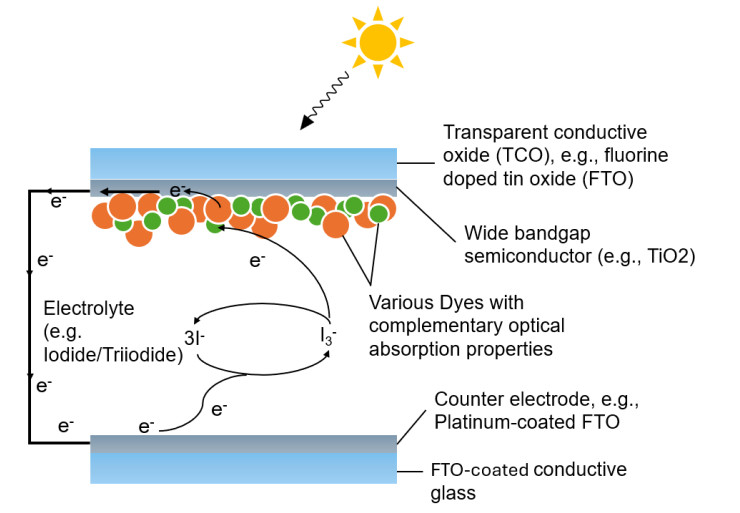
Figure 6. Schematic structure of co-sensitized DSSCs. The co-sensitization is performed by combining multiple dyes (green and orange circles) with complementary absorption ranges, widening the cell's overall absorption range and effectively mitigating spectral mismatch losses.
Through the association of light-absorbing dyes (sensitizers) with wide-bandgap semiconductor materials, DSSCs can harvest a large fraction of the incident sunlight. Dyes used as sensitizers in DSSCs are classified into metal complex dyes, metal-free organic dyes, and natural dyes. The most common and extensively investigated sensitizers in DSSCs are ruthenium (Ru) based dyes such as N719 or N3. With such Ru-based dyes posing toxicity-related hazards to the environment during the manufacturing and disposal stage, recent developments have shown growing interest in less environmentally hazardous alternative sensitizers. Consequently, increasing research efforts have shifted toward metal-free organic dyes, quantum-dot sensitizers, perovskite-based sensitizers and even natural dyes in natural DSSCs (NDSSCs)[66]. The development of such alternative sensitizers is also economically motivated, with organic or metal-free alternative sensitizers being less expensive than Ru-based dyes.
Similar to how spectral mismatch losses are mitigated in MJ solar cells by increasing the absorption range and pattern through the integration of multiple absorber materials, the absorption characteristics of DSSCs may be improved by broadening the absorption range via co-sensitization using multiple dyes with complementary optical absorption properties[67] as shown in Figure 6. With co-sensitization, limitations imposed by the narrow spectral range of individual sensitizers in DSSCs can be effectively overcome[68]. To further broaden the absorption range and thus further improve solar energy harvesting, co-sensitized DSSCs may be arranged in tandem configurations. In addition to enhancing performance by broadening the absorption range, co-sensitization fosters improvements in efficiency through the suppression of charge recombination and increases in V
A recent experimental study reporting on the electrical characterization of an N3-sensitized DSSC co-sensitized with the novel metal-free organic N-1 dye resulted in a near doubling of the device's PCE from 5.42% achieved by the N3 dye alone to 10.18% for the co-sensitized system (PCE enhancement of 87.8%)[69]. Co-sensitization of two metal-free organic dyes, MS5 and XY1b, resulted in a similarly impressive PCE enhancement of 68.8% (from 8.0% for MS5 alone to 13.5% for MS5 + XY1b)[70]. Furthermore, recent research literature has investigated ternary systems, in which multiple co-sensitizers are employed. An example for such a ternary system is the co-sensitization of the ruthenium-based metal complex dye N-719 with two metal-free organic dyes, MO-1 and MO-2, resulting in a PCE enhancement of 49.1% (from 7.35% for N719 alone to 10.96% for the ternary system)[71]. Test conditions, electrical characterizations, and PCE enhancements reported in recent experimental studies investigating co-sensitization of DSSCs are summarized in Table 3.
Electrical characterizations of co-sensitized DSSCs under unconcentrated (one sun) irradiance reported in experimental studies
| Co-sensitization of DSSCs | ||||||||||
| Main sensitizer | Test conditions | Main-sensitizer PCE [%] | Co-sensitizer(s) | Co-sensitized PCE [%] | Voc [V] | Jsc [mA/cm2] | FF [%] | Relative PCE increase [%] | Year | Source |
| N3* | Experimental - AM1.5 - WXS-155S-10 solar simulator | 5.42 | N-1** | 10.18 | 0.75 | 19.12 | 71 | 87.8 | 2024 | [69] |
| MS5** | Experimental - AM1.5G | 8 | XY1b** | 13.5 | 1.05 | 15.84 | 81.3 | 68.8 | 2021 | [70] |
| N719* | Experimental - AM1.5 - WXS-155S-10 solar simulator | 7.35 | MO-1** and MO-2** | 10.96 | 0.725 | 20.17 | 75 | 49.1 | 2024 | [71] |
| N719* | Experimental - AM1.5 - WXS-155S-10 solar simulator | 7.9 | FM-1** and SQ-2** | 11.76 | 0.788 | 25.01 | 59.7 | 48.9 | 2025 | [72] |
| N719* | Experimental - AM1.5 - WXS-155S-10 solar simulator | 7.27 | MOS-1** and MOS-2** | 10.45 | 0.734 | 18.5 | 77 | 43.7 | 2023 | [73] |
| H7** | Experimental - AM1.5G | 9.8 | XY1b** | 13.7 | 1.051 | 15.89 | 82.1 | 39.8 | 2025 | [74] |
| BIM26** | Experimental - AM1.5G - Solar simulator (96000, Newport) | 4.56 | BIM37** - CDCA as co-adsorbent | 6.3 | 0.794 | 13.22 | 60 | 38.2 | 2024 | [75] |
| N719* | Experimental - AM1.5G - Verasol ORIEL LSS-7120 solar simulator | 8.99 | R-250** | 10.92 | 0.89 | 15.86 | 75.9 | 21.5 | 2021 | [76] |
DSSCs are fabricated using low cost techniques such as inkjet/screen-printing or the roll-to-roll technique[77], making this cell type an economically viable alternative to other solar cell technologies. DSSCs are fabricated at ambient temperatures and are less prone to contamination[78]. Several technological advantages point towards the high potential of DSSCs to play a major role in future PV developments: DSSCs exhibit shorter payback times for both energy and CO2. Depending on the utilized sensitizers, DSSCs additionally hold the potential to minimize toxicity[79]. DSSCs achieve relatively high PCEs even under low light intensity conditions at dawn, dusk, or during cloudy weather. Such spectral robustness makes DSSCs a promising candidate particularly for indoor applications[80]. DSSCs exhibit remarkable power generation characteristics in environments and times of low light intensity. Furthermore, DSSCs exhibit a reduced sensitivity to changes in the incident light angle on the cell, potentially eliminating the need for a mechanical light tracking system[81]. Despite improved spectral robustness, spectral variations throughout the course of a day due to changing solar zenithal angles impact the DSSC's power generation in real-world integration cases, facilitating either spectral gains or losses.
NDSSCs use organic dyes at different degrees of purification as an alternative to synthesized dyes. With their cost-effectiveness and environmental friendliness, NDSCCs hold potential not only in producing green energy but also in establishing an environmentally friendly production of solar power plants[76]. Common examples for natural dyes employed in NDSSCs include natural pigments from fruits such as anthocyanins (which are responsible for fruits' different colors)[82], natural dyes extracted from cereal grains such as black rice[83] or from flowers such as Begonias, Perillas, or different rose types[84], or natural carotenoids from plants algae such as kelp (which are yellow, orange, and red pigments)[85]. Among the major challenges that NDSSCs face is their low conversion efficiency. Future research may lead to efficiency breakthroughs in NDSSCs up to 14% or higher, which have already been achieved by synthetic dye-based DSSCs[86].
Two major challenges of DSSCs compared to silicon-based technologies are their generally lower efficiency and shorter life-times[87]. Particularly, the relatively low V
To reduce transmission of low-energy photons and increase the chance of absorption, the path length of light within the cell can be increased either by increasing the film thickness beyond 10 μm or employing light trapping techniques. For DSSCs, confining incident light can be achieved by structures with dispersed TiO2, which cause multiple scattering[89]. The cell's performance can be improved by installing a special silver back-reflecting layer[90]. Using graphene-TiO2 composite photoanodes has achieved a relative improvement of 59% to reach a PCE of 4.28%[91]. Concerning ruthenium-based dyes, however, further breakthroughs in cost and efficiency have appeared to be increasingly less likely[78].
Hot carrier and hybrid thermoelectric solar cells
HCSCs have the potential for breaking the Shockley-Queisser limit[92]. The idea of HCSCs was first proposed in 1982. HCSC technology attempts to harvest the excess energy of so-called hot-carriers (electrons excited past the bandgap energy by high energy photons) by establishing a steady-state hot carrier distribution that can capture the excess kinetic energy of hot carriers. By extracting hot carriers and delivering them to the electrodes of a given cell prior to having fully cooled down, their surplus energy would partially contribute to an additional electrical output[93]. This reduces thermalization losses and effectively mitigating spectral mismatch.
In the case of complete harvesting of surplus energy in hot carriers, the collected energy per extracted electron-hole pair is larger than the bandgap energy[20]. HCSCs may achieve a maximum PCE of 66% according to thermodynamic calculations for single junction cells with an ideal bandgap of 0.7 eV to 0.9 eV, assuming full absorption of photons with greater energy than the bandgap energy under 1 sun illumination if the energy of such hot carriers is fully harvested before the cells cool back to the lattice temperature[94]. Under the same assumptions, the PCE of single junction solar cells may reach ~85% at maximum solar concentration.
The extraction of high-energy hot carriers can only be achieved when the cooling process is greatly slowed and/or the extraction is greatly accelerated. Hot carrier collection is achieved by introducing selective energy contacts around the absorber material which only allow the passing of hot electrons and hot holes within a narrow energy window, respectively, and in doing so prevent heat flow back toward a cold carrier population[93]. The conceptual design of the HCSC is visualized in Figure 7, where E
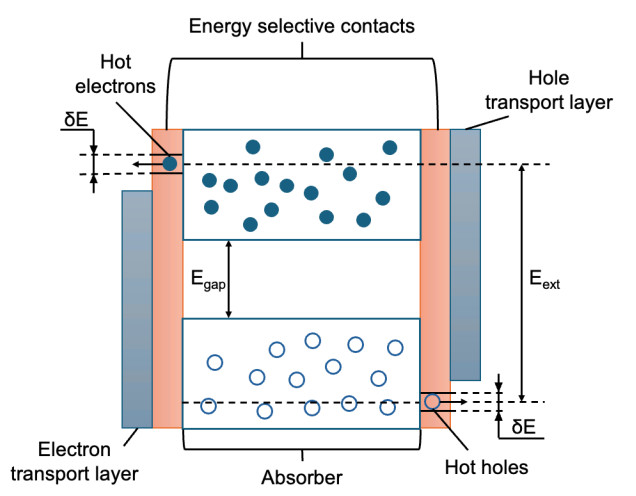
Figure 7. Schematic design of HCSC's, visualizing the hot carriers (electrons). Spectral mismatch losses are reduced by capturing the hot carrier's excess thermal energy.
Simulations have shown that for a 10,000× concentrated AM1.5D solar spectrum, both the incident power that is being absorbed and that which is being lost through thermalization decrease significantly with decreasing absorber thickness[20]. Therefore, to enable and maintain sufficient absorption and allow for efficiency improvements in ultrathin absorber layers, enhanced light trapping techniques are required.
Unfortunately, as of today, experimental work to realize the concept of HCSCs is scarce due to the difficulty of finding suitable absorber materials in which cooling is sufficiently slowed down to allow for the extraction of hot carriers while maintaining the absorber's ability to absorb a wide spectral range. Energy selective contacts with a narrow density of states at an appropriate energy level need to be engineered in order to suppress cooling through the contacts and leakage of hot carriers[92]. HCSCs were shown to have higher spectral robustness compared to tandem devices, implying a reduced sensitivity to spectral variations due to changing solar zenithal angles throughout the day[95]. Substantially reduced current density as caused by insufficient extraction of widely distributed hot electrons through the requisite energy selective contact can severely limit the performance of HCSCs[96].
Another promising technology that has been studied in conjunction with PV's is thermoelectric (TE) generators. These hybrid solar systems work by repurposing unused heat generation from solar cells into electricity using the TE generators. TE's generally work best in the IR range of the solar spectrum, which is typically below the bandgap of standard PV cells, thereby effectively extending the usable solar spectrum range of a PV system[97]. These generators work by utilizing the Seebeck effect, first discovered by Thomas Seebeck in 1821, which operates on the principle that a temperature difference between two different materials creates a potential difference relative to the temperature gradient, inducing a current flow.
A TE generator is made of multiple TE couples connected in series electrically and in parallel thermally consisting of p-type and n-type semiconductor materials[98]. A temperature difference across the TE generator causes electrons and holes to travel from the hot end to the cold end of the couple, where they recombine and cause a current flow through the connected external load. This technology has been applied in conjunction with PV technology to harvest unused heat from photons under the bandgap within the IR spectral region, as well as for collecting heat due to thermalization within the solar cell itself. To promote the temperature difference needed, a heat sink is added to the opposite side of the TE generator. This in essence allows the system to make use of a wider spectral range, thereby increasing overall system efficiency.
One study utilizing this hybrid setup found an efficiency increase from 12.5% to 16.3% by incorporating TE's into c-Si solar cells to harvest losses from both thermalization and transmission[99]. Another study found that incorporating TE's into MJ solar cells also helped to offset losses due to thermalization. This hybrid MJ system achieved maximum efficiency values of ~32% under concentrated sunlight[100]. A major contribution to the efficiency increase of this system was from the TE's cooling effect on the PV, while only a smaller contribution to efficiency increases were from energy generation from the TE itself. This presents the notion that TE's can be utilized to improve PV efficiency by other methods besides from their own power generation. In addition to this, research has been proposed to incorporate heat storage devices into hybrid solar cell systems in order to continue power generation during the night. During the day, heat storage devices collect heat either by raising temperature or with the use of phase change materials[101]. At night this heat can be used by TE generators to generate power when solar cells are unable to, allowing for full-time power generation. Currently there are limited studies on utilizing this technology with hybrid solar systems. Furthermore, the costs involved by incorporating TE technology into PV's are high. The addition of BiTe TE modules increases the cost per meter of a standard Si panel from ~400 $/m2 to ~2,100 $/m2[102].
Quantum dot solar cells
IBSCs were proposed in 1997 as an alternative to tandem solar cells, promising ultra-high solar-electricity energy conversion[103]. IBSCs reduce spectral mismatch losses that occur due to non-absorption (transmission) by introducing absorber materials with one or more distinct intermediate bands between the conduction and valence bands of an otherwise conventional semiconductor material[104]. The schematic working principle of IBSCs based on multi-photon excitation is visualized in a bandgap diagram in Figure 8. Here, E
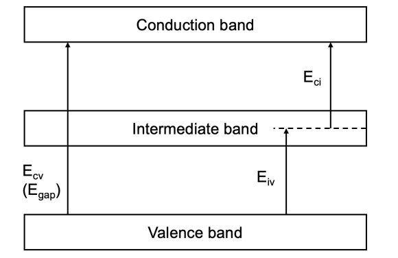
Figure 8. Energy band diagram of IBSCs allowing for excitation processes to intermediate energy bands, effectively allowing the absorption of lower energy photons and thus enhancing the cell's absorption range.
Optimizing the energy levels of the bands for IBSCs reveals a thermodynamic efficiency limit of 74.6% when four intermediate bands are included. IBSCs with one intermediate band exhibit a limiting efficiency as high as 63.2% under maximum solar concentration (46,050 suns) for optimum energy separations of E
Quantum dot solar cells (QDSCs) mitigate spectral mismatch by utilizing Quantum Dots (QDs) that offer tunable bandgaps to optimize the cell's absorption spectrum. QDs are nanometer-sized semiconductor particles that confine charge carriers in all three dimensions, create discrete energy levels, enable precise energy selection, and act as real energy selective contacts. Bandgap tuning is achieved via size variation of the QDs.
Popular QD materials investigated in literature include lead-based materials such as lead chalcogenides (PbS, PbSe, and ternary alloys such as PbSxSe
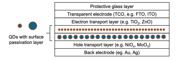
Figure 9. Common structure of a colloidal QDSC in which spectral mismatch is mitigated by fine-tuning the bandgap of the QDs.
To improve photostability of the QDSC, enhance carrier mobility and decrease the negative effects of carrier recombination, surface passivation layers may be added to the QDs, effectively leading to advances in the achieved PCE. For example, by optimizing the surface passivation of PbS QDs, an overall PCE of 9.6% was achieved[109].
Provided a sufficient density of QDs embedded or grown within a host material, energy separation of the QD levels from both the valence and conduction band, and strong dot-to-dot coupling, the discrete quantum dot energy levels can hybridize into discrete intermediate bands. Such a distinct energy level can be achieved through variation of size, density and coupling of the QDs. If the distinct QD-generated energy band is entirely within the host bandgap acting as a long-lived carrier reservoir and supporting two-step photon absorption, the device effectively acts as an IBSC. In this case the device would be referred to as a quantum dot intermediate band solar cell, or QDIBSC.
Investigating the impact of different Sb compositions in a type-II GaAsSb capping layer of a QDSC incorporating an InAs QD layer, an Sb composition of 18% yielded the high measured PCE of 17.31% under unconcentrated AM1.5G irradiance. This PCE increase can be attributed to a rising GaAsSb valence band with increased Sb compositions. The obtained PCE corresponds to an 11.25% increase compared to type-I InAs/InGaAs QDSCs[110].
Inadequate light collection efficiency and the influence of charge recombination could be the primary reasons for low PCEs of QDSCs compared to conventional SSCs or even emerging PSCs. Aiming to minimize charge recombination, passivation layers may be incorporated directly around the QDs or between layers of the QDSC structure. Better utilization of sunlight may lead to further efficiency improvements for QDSCs. For example, by additionally depositing black phosphorus QDs onto a ZCISSe QD-sensitized TiO2 electrode, the photoanode's light capture ability was enhanced, resulting in a PCE of 15.66% under unconcentrated (one sun) AM1.5G irradiance[111].
In order to optimize QDSCs for operation under concentrated sunlight, a QD based InAs/GaAs device was equipped with a InGaP top cell in order to prevent extreme over-generation of electric current on account of the very low transition energy of InAs QD's of only around 0.3 eV[112]. By using this design approach, the short circuit current density J
Table 4 lists electrical characterizations featuring notable PCE achievements reported in recent experimental studies investigating a variety of QD based PV devices.
Electrical characterizations of QD based PV devices under unconcentrated (one sun) irradiance reported in experimental and numerical studies
| QDSCs | |||||||
| Material | Test conditions | Voc [V] | Jsc[mA/cm2] | FF [%] | PCE [%] | Year | Source |
| InAs QDs with GaAs0.82Sb0.18 capping layer | Experimental - AM1.5G | 0.85 | 28.19 | 72.37 | 17.31 | 2023 | [110] |
| Black phosphorus (BP) QDs deposited onto ZCISSe-QD sensitized TiO2 electrode | Experimental - AM1.5G | 0.816 | 26.88 | 71.4 | 15.66 | 2023 | [111] |
| ZnSe shell layer around ZCISe QDs | Experimental - AM1.5G - Oriel 94022A solar simulator | 0.77 | 26.69 | 66.8 | 13.71 | 2020 | [113] |
| ZCISe and CdSe sequentually deposited onto TiO2 film | Experimental - AM1.5G | 0.752 | 27.39 | 61.9 | 12.75 | 2018 | [114] |
| PbS-oleic acid (OA) QD solution forming n-type PbS-PbX2 QDs | Experimental - AM1.5G | 0.643 | 29.36 | 66.37 | 12.53 | 2024 | [115] |
| CdSe/ZnS core-shell QD layer between ZnO/MoO3 thin-films | Experimental - AM1.5G - Newport 96000 Xenon arc lamp with filter | 1.9 | 9 | 67 | 11.4 | 2025 | [116] |
Quantum well solar cells
Quantum Well Solar Cells (QWSCs) incorporate Quantum Wells (QWs) in the form of thin layers of semiconductor material within otherwise conventional wider bandgap semiconductor materials. QWs enable spectral mismatch mitigation by creating new, tunable energy states, effectively allowing the absorption of previously sub-bandgap photons towards the IR end of the incident spectrum. State of the art QW based PV devices further enhance absorption characteristics by employing multiple QWs. The effective bandgap of QW structures is influenced by quantum size effects, quantum confined stark effects, and stress effects[117]. QWs do not act as isolated intermediate bands due to their inability to sustain independent quasi-Fermi levels, and do not act as long-lived carrier reservoirs. Therefore, unlike in IBSCs using supplementary two-step photon absorption, QW based devices generally rely on standard photogeneration followed by carrier escape/extraction from QWs into the surrounding conduction band via thermionic emission or (thermally assisted) tunneling[118]. As opposed to QDs, which confine charge carriers in all three dimensions, QWs restrict charge carrier movement to two dimensions in the plane of the well. Because QWs merely act as potential steps, a lower maximum PCE is expected than for QD-based energy selective contacts. Both QW and QD nanostructures can be applied to reduce entropy loss[92].
By incorporating strain-balanced GaAsP/GaInAs QWs into III-V two-junction GaInP/GaAs and single-junction GaAs PV devices, PCEs of 32.92% and 27.18% were achieved, respectively[119]. Recently, exploration of high-efficiency solar cells that integrate QDs into QW structures (commonly referred to as DWELL, meaning Dot in Well) has shifted into focus. In 2024, a remarkable PCE of 31.8%[120] was numerically simulated using the SCAPS-1D software by effectively creating intermediate energy levels using CdTe QDs embedded in Al0.3Ga0.7As/GaAs QWs with an open circuit voltage V
Electrical characterizations of QW based PV devices under unconcentrated (one sun) irradiance reported in experimental and numerical studies
| QWSCs | |||||||
| Material | Test conditions | Voc [V] | Jsc[mA/cm2] | FF [%] | PCE [%] | Year | Source |
| GaAsP/GaInAs QWs in 2J GaInP/GaAs cell | Experimental - AM1.5G - Class A solar simulator | 2.5 | 15.36 | 85.7 | 32.92 | 2021 | [119] |
| GaAsP/GaInAs QWs in single junction GaAs solar cell | Experimental - AM1.5G - Class A solar simulator | 1.04 | 31.48 | 82.98 | 27.18 | 2021 | [119] |
| 2D perovskite QWs using p-F-PEAI spacer molecules | Experimental - AM1.5G | 1.146 | 25.67 | 85.11 | 25.03 | 2024 | [121] |
| GaInP solar cell with 5 InP QWs | Numerical simulation - AM1.5G - Silvaco Atlas TCAD simulation tool | 1.432 | 19.04 | 85.83 | 22.41 | 2020 | [122] |
Spectral conversion
With decades of research dedicated to the optimization and modification of the cell's electronic properties itself, further reduction of spectral mismatch losses enabling advances in solar cell conversion efficiency are anticipated through spectral conversion[123]. Spectral conversion involves modifying the incident spectrum through luminescent conversion processes, which generates photons tailored to the absorption characteristics of different PV devices, effectively extending the cell's light-harvesting range. Spectral conversion is facilitated in PV devices by incorporating passive luminescent materials, which do not rely on external energy inputs such as electrical excitation. Available spectral conversion mechanisms are summarized in Table 6.
| Mechanism | Description |
| Upconversion (UC) | At least two lower-energy photons are combined into one high-energy photon which can then be absorbed by the cell |
| Downconversion (DC) | One high-energy photon is transformed into two lower-energy photons closer to the cell's bandgap energy, reducing thermalization losses |
| Downshifting (DS) | One high-energy photon is transformed into one lower-energy photon closer to the cell's bandgap energy, reducing thermalization losses |
Efficiency enhancements of up to 32% for DC systems and 35% for UC systems have been predicted in c-Si solar cells[124]. PCE enhancements of up to 10% are predicted for DS systems[125]. Among the most extensively studied materials for photon conversion are lanthanides or rare-earth systems due to the suitability of their discrete energy levels inside a wide variety of host materials[126].
Upconversion
Several methods exist for the facilitation of UC technology in PV devices. Common approaches include adding UC layers or UC material-doped glass layers at the rear of bifacial solar cells, as well as the doping of photoanodes with UC nanorods or nanoparticles (NPs). Transmitted sub-bandgap photons are absorbed via sequential ground state absorption/excited state absorption processes in a three-level system. Principal UC processes include excited state absorption, energy transfer, and the photon avalanche process. Other UC processes such as cooperative UC and energy migration mediated UC are being researched. Figure 10 visualizes the principal excited state absorption UC process, where E1 is the energy for excitation from the ground state to the intermediate energy level of the upconverter material, E2 is the energy for excitation from the intermediate energy level to the top energy level, and Eg is the energy of the photon emitted upon relaxation of the electron from the top energy level to the ground state, which corresponds to the bandgap energy of the solar cell. Since the upconverting material outputs one photon for two absorbed photons, the maximum quantum efficiency of the upconverter can only be 50%. Transmission losses are generally higher for solar cells with a wider bandgap, and lower for narrower bandgaps. UC pushes the theoretical limiting efficiency of single junction SSCs, which have a bandgap of 1.12 eV, to 40.2%[127]. This is a relative improvement of almost 26% to the Shockley-Queisser limit of 32% for the same SSCs. The highest limiting efficiency of solar cells using UC systems is 50.69% for a bandgap of 2.0 eV.
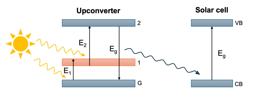
Figure 10. Band diagram for upconversion process visualizing the conversion of two low-energy photons into one photon of higher energy tuned to the bandgap of the employed solar cell.
UC systems are commonly employed in PV devices including SSCs, amorphous Si TFSCs, III-V solar cells and DSSCs[128]. Working principles include UC via rare earth ions, UC via triplet-triplet annihilation, UC via QDs, or UC via thermal radiation[16]. As previously mentioned, the impact of UC is greatest in solar cells with a bandgap above 1.25 eV. This is due to the fact that for cell's with a bandgap above 1.25 eV, transmission losses (which are mitigated by UC) outweigh losses due to thermalization of hot carriers.
While the bandgap of crystalline SSCs of ~1.12 eV (corresponding to a wavelength of 1,100 nm) is below the mark of 1.25 eV, sub-bandgap transmission are still significant in this cell type at 20%[129]. Given the magnitude of these losses and the dominance of SSCs in the solar cell market, developing cost-effective, PCE-enhancing UC technologies holds significant economic potential.
The concentration factor of the incident irradiance has a considerable impact on UC efficiency[17]. For NaYF4: Er3+, Yb3+, one of the most investigated upconverter materials, saturated quantum UC efficiencies of around 10% have been reported at about 40 W/cm-2 (400 sun concentration). At lower concentration factors of e.g. six (ca. 0.6 W/cm-2), Gd2O2S: Er3+, Yb3+, another UC material, experiences a saturated quantum efficiency of less than 1%. Aiming to increase the UC efficiency under conditions of low light intensity, the use of photoluminescent QDs in combination with UC materials has been proposed. Such photoluminescent QDs would absorb photons with energies outside of the UC response range before re-emitting UC-usable photons. Demonstrating this concept, photoluminescent PbS-QDs were dissolved together with UCs in a layer above the back reflector of a bifacial SSC, resulting in a 60% increase in photocurrent when compared to the incorporation of UC only[130]. Photonic crystal nanostructures can positively impact the direction and wavelength of a photon undergoing UC. Experiments show that PbSe QDs with InP graphite lattice photonic crystals increased vertical emissions by a factor of 7.8, significantly increasing the amount of photons that reach the cell after UC[131].
DSSCs sensitized with ruthenium-based dyes such as N719 or N749 possess bandgap energies exceeding 1.8 eV (corresponding to a wavelength of 700 nm), leading to approximately 52% of the solar energy in the incident solar spectrum not being harvested by the absorber material due to sub-bandgap transmission[129]. Consequently, considerable research efforts have been directed toward incorporating UC materials into DSSCs. One such UC material extensively investigated in contemporary research is trivalent erbium (Er3+). By doping the TiO2 membrane of an investigated DSSC with 1 wt% NaYF4: Yb3+/Er3+ nanorods annealed at 500 °C, a substantial PCE enhancement of 95.58% from 3.17% to 6.2% was achieved[132]. Besides the photoluminescent processes, the authors attribute this performance increase to improved charge separation facilitated by the nanorods.
The bandgap of PSCs is ~1.5 eV, corresponding to near-infrared light with a wavelength of 800 nm. Hence, similar to DSSCs, UC is a promising approach for the development of ultra high-efficiency PSCs. For UC-integrating PSCs under unconcentrated (one sun) AM1.5G illumination a limiting efficiency of 47.0% was calculated[127], corresponding to a relative increase of 42.8% compared to the limiting efficiency of 32.91% for the same devices without UC NP[133]. Experimental studies on UC technologies incorporated into PSCs have shown promising PCE enhancements. For example, by mixing high-fluorescence NaYbF4: Ho3+ UC NPs into ZrO2 paste at 40 wt%, drying, annealing, and finally incorporating the resulting film as a scaffold layer in a FA0.4MA0.6PbI3 PSC under unconcentrated (one sun) AM1.5G irradiance, the device's PCE was increased by 28.8% from 11.12%, resulting in a UC-enhanced PSC of 14.32%[134]. It is important to note that this PCE enhancement cannot be solely attributed to UC processed, but also to a decrease in recombination rate and trap-state density, as well as accelerated charge transfer and extraction. Further electrical characterizations of DSSCs and PSCs incorporating a variety of UC materials reported in recent literature yielding notable PCE enhancements are summarized in Table 7.
Electrical characterizations and PCE enhancements of several UC materials employed in DSSCs and PSCs under different irradi-ances reported in experimental studies
| UC technology employed in DSSCs | |||||||||
| Material | Test conditions | Voc [V] | Jsc[mA/cm2] | FF [%] | PCE w/o UC [%] | PCE w/UC [%] | Relative PCE increase [%] | Year | Source |
| TiO2 layer doped with Gd2O3: Ho3+/Yb3+ rectangular microrods (annealed at 800 °C for 3 h) | Experimental - Philips R125 IR 250 infrared heat lamp - 120 W/m2 - 30 cm above cell | 0.6 | 25 | 48.1 | 3.44 | 7.22 | 109.9 | 2025 | [135] |
| TiO2 layer doped with NaYF4: Yb3+/Er3+ nanorods (1.0 wt%, annealed at 500 °C) | Experimental - AM1.5 | 0.76 | 10.6 | 77 | 3.17 | 6.2 | 95.58 | 2025 | [132] |
| 69TeO2: 25Na2O: 5BaO: 1Er2O3 (Er3+ doped tellurite glass) | Experimental - AM1.5 - Oriel, Newport solar simulator | 0.67 | 6.47 | 59 | 1.68 | 2.55 | 51.78 | 2025 | [136] |
| LiYF4: Yb0.2/Er0.02/Ho0.02/Tm0.02 @LiYF4: Yb0.2 NPs modified using 4-amino-benzoic acid | Experimental - AM1.5 | 0.74 | 16.91 | 66.78 | 6.32 | 8.22 | 30.1 | 2024 | [137] |
| UC technology employed in PSCs | |||||||||
| Material | Test conditions | Voc [V] | Jsc[mA/cm2] | FF | PCE w/o UC [%] | PCE w/UC [%] | Relative PCE increase [%] | Year | Source |
| NaYbF4: Ho3+ NPs within ZrO2 as scaffold layer for FA0.4MA0.6PbI3 PSC | Experimental - AM1.5G - Oriel 91192-1000 solar simulator | 0.975 | 25.16 | 58.7 | 11.12 | 14.32 | 28.8 | 2018 | [134] |
| TiO2 layer doped with 40% YLF4: Yb, Er@YLF4: Nd core-shell NPs | Experimental - AM1.5G | 1.09 | 25.85 | 79 | 18 | 22.5 | 25 | 2025 | [138] |
| NaCsWO3-enhanced NaYF4@NaYF4: Yb, Er NPs in both hole transport layer and perovskite film | Experimental - AM1.5G - Newport Oriel solar simulator | 1.08 | 23.26 | 76 | 16.01 | 18.89 | 17.99 | 2021 | [139] |
| NaYF4: Yb, Tm@NaYF4 core-shell NPs in both hole transport layer and perovskite film | Experimental - AM1.5G | 1.2 | 26.74 | 79.57 | 22.25 | 25.49 | 14.6 | 2025 | [140] |
| TiO2 layer doped with 30% YLiF4: Yb, Er NPs | Experimental - AM1.5 - CT50AAA solar simulator | 1.104 | 24.92 | 77.5 | 19.45 | 21.32 | 9.6 | 2024 | [141] |
| TiO2 layer doped with 30%YLiF4: Yb, Er NPs | Experimental - AM1.5G | 1.067 | 20.46 | 74.3 | 15.5 | 16.22 | 4.6 | 2024 | [142] |
Downconversion
Normally, high energy photons above the cell's bandgap energy would potentially cause significant thermalization losses due to the waste of excess energy contained in hot carriers. Aiming to mitigate these thermalization losses, DC layers transform such high energy photons into two lower energy photons tailored to the cell's bandgap energy prior to absorption[143]. Schematic DC photoluminescent processes comprising excitation and emission are visualized in a band diagram in Figure 11, where Eg is the solar cells bandgap energy and the energy difference between each respective energy level in the DC material. Because of the 1-to-2 conversion ratio between absorbed and emitted photons, the quantum efficiency of the DC process cannot exceed 200%[144].
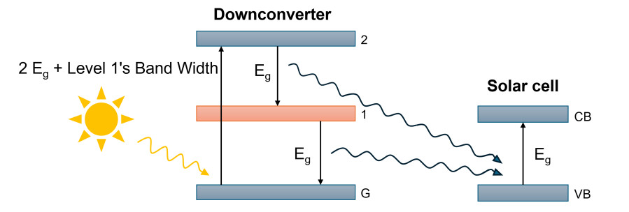
Figure 11. Band diagrams for downconversion process, showing the conversion of one high-energy photon into two photons of lower energy tuned to the employed solar cell's bandgap.
Common approaches for facilitating DC in PV devices include doping its antireflective coating layer (commonly made of ethyl vinyl acetate (EVA)) at the top surface with DC particles, incorporating the DC particles into the device's glass cover sheet, embedding DC core-shell particles into a cell's photoanode, or inserting individually function DC layers between photoanode and absorber layers[123]. In addition to PCE enhancements through mitigation of thermalization losses, DC layers placed at the front surface of a PV device based on materials such as Tb3+-Yb3+, employed e.g. as co-dopants in silicon nitride matrix layers, may consequently further improve the device's absorption characteristics through beneficial anti-reflective coating characteristics[16].
Calculations have shown a maximum efficiency of up to 38.6% for a solar cell with a bandgap energy of 1.1 eV incorporating a downconverting layer located on the front surface of the solar panel[143]. Typical DC mechanisms include quantum cutting using host lattice states, quantum cutting on single rare-earth ions, or DC using rare-earth ion pairs[123]. In quantum cutting using host lattice states describes, a high-energy UV photon excites the host lattice. The energy is then transferred to luminescent centers, where two photons in the visible or infrared range are emitted. Quantum cutting on single rare-earth ions typically involves sequential energy transitions within the ion's multiple excited states. A UV photon excites a single rare-earth ion to a high-energy state, which then relaxes in two steps, emitting two photons with lower energies. Finally, DC using rare-earth ions involves the excitation of a donor ion, which then transfers part of its energy to a neighboring acceptor ion, resulting in the emission of lower energy photons by both ions.
Downconverting materials have been applied to a wide range of PV technologies, including SSCs, DSSCs, or QDSCs[145]. DC is commonly facilitated by lanthanide and transition-metal ion activated materials. The absorption range is broadened by introducing sensitizers with spin-allowed transitions and by combining the advancing perovskite QDs, nanostructures, and organic dye molecules[146].
Remarkable PCE enhancements in SSCs facilitated by luminescent DC processes have been reported in contemporary research. By installing a hydrothermally treated vinyl acetate ethylene (VAE) coating with 0.6 wt% dispersed carbon QDs on the top surface of a SSC, a remarkable PCE increase from 6.5% to 8.1% (corresponding to a 24.6% increase) was achieved under unconcentrated AM1.5G irradiance produced by a solar simulator[147].
Substantial PCE enhancements have also been reported in recent literature where DC technology is employed in PSCs. For example, the embedment of ZnGa2O4: Eu3+ nanophosphor particles into the TiO2 electrode of an investigated PSC increased its initial bare-cell PCE of 10.67% to 13.8% under unconcentrated (one sun) AM1.5G irradiance, which corresponds to a relative PCE enhancement of 29.33%[145]. This PCE enhancement is accompanied by a strong increase in short-circuit current from 20.12 mA/cm2 of the bare cell to 23.68 mA/cm2 of the nanophosphor-enhanced cell. In addition to the positive impact of DC, the authors attribute the reported performance enhancement to improved exciton generation rates. The cell retained roughly 66% of its initial efficiency when stored for nine days in ambient air between 21-23 °C at a relative humidity of 40%-45%.
Finally, by embedding YVO4: Eu3+, Bi3+@SiO2 core-shell particles at a 10% weight ratio within a nanostructured TiO2 layer, substantial PCE enhancements were reported for an investigated DSSC. In addition to facilitating DC, the particles, which were prepared using the sol-gel method, lead to notably enhanced light scattering, extending the path light takes within the cell and thus effectively increasing the probability of absorption. The combined effects of light scattering and DC led to a significant relative increase in PCE of 64% from the initial 3.6% of the bare cell to 5.9% under simulated, unconcentrated (one sun) AM1.5G irradiance.
Emerging research trends emphasize the development of hybrid nanomaterials which merge UC and DC technology, enabling simultaneous conversion of both near-infrared and UV photons while emitting visible light tailored to a cell's absorption range. UC/DC hybrid nanomaterials are commonly lanthanide-doped materials. For example, employing NaYF4: Yb3+/ Er3+@ NaYF4: Eu3+ core-shell hybrid UC/DC NPs in a N719-sensitized DSSCs enhanced the device 's PCE from 6.726% to 7.664% under unconcentrated (one sun) AM1.5G illumation, corresponding to a relative increase of 13.95%[148]. A portfolio of recent electrical characterizations reported in experimental studies on DC technologies employed in SSCs, PSCs, and DSSCs is presented in Table 8.
Electrical characterizations and PCE enhancements of several DC materials employed in SSCs, PSCs, and DSSCs under uncon-centrated (one sun) irradiance reported in experimental studies
| DC technology employed in SSCs | |||||||||
| DC material | Test conditions | Voc [V] | Jsc[mA/cm2] | FF [%] | PCE w/o DC [%] | PCE w/DC [%] | Relative PCE increase [%] | Year | Source |
| Si-rich oxide (SRO) film (thickness 85 nm, annealed for 80 min. @ 1100 °C) with embedded Si nanocrystals covering c-Si cell | Experimental - AM1.5 - Solar simulator (2A, Oriel Newport) | 0.54 | 35 | 74 | 9.4 | 13 | 38.3 | 2017 | [149] |
| 0.6 wt% carbon QDs dispersed in vinyl acetate ethylene (VAE) coating covering top cell surface | Experimental - AM1.5G - YSS-150A Yamashita Denso solar simulator | 0.61 | 20.5 | 64 | 6.5 | 8.1 | 24.6 | 2026 | [147] |
| Yb3+/Ce3+ codoped CsPbCl1.5Br1.5 perovskite QD coating (thickness 230 nm) on top of SSC | Experimental - AM1.5G | 0.65 | 39.8 | NA | 18.1 | 21.5 | 18.8 | 2017 | [150] |
| Glass coating doped with 1% Eu2O3, 0.5% ZnO, and 0.5% AgNO3 | Experimental - AM1.5 @ 25 °C - Newport, LCS-100 solar simulator | 0.58 | 15.55 | 61.41 | 11.9 | 13.85 | 16.39 | 2025 | [151] |
| Ce3+-Yb3+ co-doped YAG phosphors dispersed in ethyl vinyl acetate (EVA) coating on top of c-Si cell | Experimental - AM1.5 - AAA XJCM-9 solar simulator | 0.63 | 35.64 | 74 | 15.96 | 16.63 | 4.2 | 2019 | [144] |
| DC technology employed in PSCs | |||||||||
| DC material | Test conditions | Voc [V] | Jsc[mA/cm2] | FF [%] | PCE w/o DC [%] | PCE w/DC [%] | Relative PCE increase [%] | Year | Source |
| ZnGa2O4: Eu3+ nanophosphor incorporated into TiO2 layer of PSC | Experimental - AM1.5G | 0.94 | 23.68 | 62 | 10.67 | 13.8 | 29.33 | 2016 | [145] |
| EuW10 polyoxometalate incorporated into TiO2 layer of a hole transport material-free PSC | Experimental - AM1.5G | 0.88 | 23.46 | 72.4 | 11.42 | 14.36 | 25.7 | 2020 | [152] |
| Cerium-based microcrystal (CDM) layer deposited onto c-TiO2 layer of (CsFAMA)Pb(BrI)3 based PSC | Experimental - AM1.5 | 1.09 | 24.09 | 76.65 | 17.11 | 20.13 | 17.7 | 2025 | [153] |
| Sr2CeO4: Eu3+ individually functioning DC layer between c-TiO2 film and (CsFAMA)Pb(BrI)3 perovskite layer | Experimental - AM1.5 | 1.06 | 23.7 | 75.53 | 16.6 | 18.95 | 14.15 | 2019 | [154] |
| CsPbCl3: Mn2+ QD DC layer at SnO2/perovskite interface | Experimental - AM1.5G - Oriel Model 94043 solar simulator | 1.21 | 24.3 | 80.35 | 21.26 | 23.61 | 11.1 | 2025 | [155] |
| ZnO NPs dispersed onto PSC glass layer | Experimental - AM1.5 | 0.937 | 19.44 | 61.4 | 10.6 | 11.19 | 5.5 | 2024 | [156] |
| DC technology employed in DSSCs | |||||||||
| DC material | Test conditions | Voc [V] | Jsc[mA/cm2] | FF [%] | PCE w/o DC [%] | PCE w/DC [%] | Relative PCE increase [%] | Year | Source |
| YVO4: Eu3+, Bi3+@SiO2 core-shell particles embedded into photoanodes (at 10% weight ratio) | Experimental - AM1.5G - Abet 2000 Class AAB solar simulator | 0.687 | 13.44 | 64.4 | 3.6 | 5.9 | 64 | 2014 | [157] |
| Lanthanide(Sm3+)-doped TiO2 electrodes | Experimental - AM1.5 - Xenon arc lamp in ambient atmosphere | 0.81 | 10.9 | 67 | 4.23 | 5.81 | 37.4 | 2011 | [158] |
| 0.9MW % Eu3+: MgAl2O4 DC phosphor added to TiO2 NPs | Experimental - AM1.5G | 0.642 | 14.8 | 62 | 3.9 | 4.8 | 23.1 | 2024 | [159] |
| 3 wt% La3+-doped TiO2 NPs (synthesized via sol-gel method) | Experimental - AM1.5G - Oriel-SOL3A Class-AAA solar simulator | 0.84 | 10.96 | 63.15 | 4.75 | 5.82 | 22.5 | 2025 | [160] |
Downshifting
In the DS process, a high energy photon is absorbed by the DS material followed by the emission of one lower energy photon at a longer wavelength (typically in the visible/near-infrared region). Therefore, similar to DC, DS aims to mitigate thermalization losses caused by high energy photons with unusable excess energy beyond the bandgap of a PV absorber material. Similar to the UC and DC photoluminescent processes, efficiency enhancements can be achieved through DS since incoming high-energy photons are tailored to the cell's absorption characteristics prior to reaching the cell's photoconductive layers[161].
The DS process consists of the initial electron excitation, followed by a two-step sequential relaxation process, as visualized in the bandgap diagram in Figure 12. The first relaxation step is non-radiative from the top energy level to the intermediate band of the DS material. During the second, radiative relaxation, a photon of the bandgap energy Eg is emitted for absorption by the solar cell.
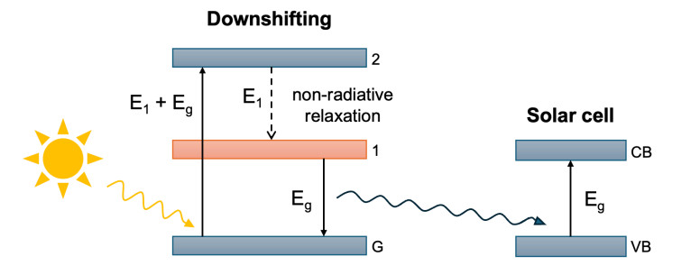
Figure 12. Band diagram for DS process visualizing the conversion of one high-energy photon into one low-energy photon tuned to the employed solar cell's bandgap.
Since only one photon is emitted for each absorbed photon, the quantum efficiency of a DS process followed by ideal abosrption cannot exceed 100% (one excited electron per one incident photon)[144].
By fabricating two SiO2 layers containing unique DS-facilitating phosphors on the top surface of a SSC via a spin-on coating process, a pronounced increase in EQE in the spectral range between 350 and 1,000 nm from 52.93% for the bare cell to 68.17% for the DS-enhanced cell was obtained[162], indicative of the ability of DS to widen the cell's effective light harvesting range. This EQE enhancement manifests itself in the form of a substantial 28.91% increase in short-circuit current and 31.63% PCE enhancement (from 11.14% to 14.66%). While the authors attribute this PCE enhancement exclusively to the DS phosphors, the integration of DS technology into host materials commonly facilitates a range synergetic effects beneficial to the PV device's performance. For example, by combining plasmonic scattering effects of silver NPs with the luminescent DS effects of Eu-doped phosphor, the PCE of an investigated SSC was increased from 11.31% to 14.27%, which corresponds to a substantial relative PCE enhancement of 26.17%[163].
DS may also be integrated into multipurpose textured anti-reflection films[164]: incorporating (Ba, Sr)2SiO4: Eu2+ micron phosphor as a DS material into textured polydimethylsiloxane films at the front of a perovskite/silicon tandem solar cell yielded PCE enhancement through combined effects of the antireflective control for the top cell, enhanced light trapping, and DS benefits. A 14.9% relative PCE enhancement from 20.1% to 23.1% was observed. The antireflective film alone raised the efficiency from 20.1% to 22.3%, which was then further increased by another 3.6% through the DS phosphors.
Recent literature has investigated hybrid nanomaterials merging UC and DS. In a recent 2025 study, a pronounced PCE enhancement of 22.19% was achieved in a PSC through simultaneous and spatially selective doping of Er3+ and Eu3+ lanthanides into the core and shell of nanomaterials[165]. The resulting hybrid NaGdF4: Yb3+, Er3+@NaGdF4: Eu3+ NPs were incorporated in the PSC as an interfacial layer, facilitating both UC and DS. The authors attribute this improvement to a highly efficient DS process and reduced nonradiative recombination, while pointing out that the contribution of UC requires further confirmation.
Table 9 summarizes additional electrical characterizations reported in experimental studies of DS technology employed in SSCs, showing the potential of DS to significantly enhance the PCE of fabricated PV devices.
Electrical characterizations and PCE enhancements of several DS materials employed in SSCs under unconcentrated (one sun) irradiance reported in experimental studies
| DS technology employed in SSCs | |||||||||
| DS material | Test conditions | Voc [V] | Jsc[mA/cm2] | FF [%] | PCE w/o DS [%] | PCE w/DS [%] | Relative PCE increase [%] | Year | Source |
| (Sr0.9Ba0.1)3SiO5: Eu (Phosphor-G) and [(Sr0.05Ba0.95)0.98Eu0.02]2SiO3.9F0.1 (Phosphor-E) within stacked SiO2 layers on n+-Si emitter | Experimental - AM1.5G - XES-151S solar simulator | 0.547 | 34.69 | 77.19 | 11.14 | 14.66 | 31.63 | 2022 | [162] |
| Coating comprising Ag NPs embedded in SiO2 ARC mixed with 3 wt% Eu-doped phosphors | Experimental - AM1.5G | 0.55 | 32.85 | 79.02 | 11.31 | 14.27 | 26.17 | 2018 | [163] |
| ZnO NPs coating for Si substrate (thickness 98 nm, functions as DS layer and anti-reflection coating) | Experimental - AM1.5G - Oriel Sol3A solar simulator | 0.591 | 31.29 | 56.03 | 8.65 | 10.36 | 19.77 | 2022 | [166] |
| (Sr0.9Ba0.1)3SiO5: Eu (Phosphor-G) within SiO2 LDS layer on n+-Si emitter | Experimental - AM1.5G - XES-151S solar simulator | 0.548 | 30.97 | 77.01 | 11.14 | 13.07 | 17.39 | 2022 | [162] |
| Core-shell CdSe/CdS QDs deployed on window side of c-Si cell | Experimental - AM1.5G, STC - Oriel Sol2A solar simulator | 0.546 | 37 | 67 | 12 | 13.5 | 12.5 | 2017 | [167] |
| Ce3+-doped YAG phosphors dispersed in ethyl vinyl acetate (EVA) coating on top of c-Si cell | Experimental - AM1.5 - AAA XJCM-9 solar simulator | 0.63 | 34.95 | 73 | 15.71 | 16.06 | 2.23 | 2019 | [144] |
CONCLUSION
Spectral mismatch is the predominant limiting factor in converting light to usable electricity via solar PV panels. Due to inefficient absorption of bandgap-misaligned photons, approximately 60%-65% of the total energy losses in conventional c-Si solar cells are governed by spectral mismatch. Consequently, even incremental technological advances in the mitigation of spectral mismatch are of considerable importance amid a rapidly growing global demand for solar energy. The state-of-the-art and efficiency improvement potential of several spectral mismatch mitigation technologies were reviewed on the basis of numerous contemporary experimental and numerical studies. The reviewed technologies were separated into two categories: cell modification, encompassing cell technologies with optimized absorption characteristics, or spectral modification, describing photoluminescent processes in which misaligned photons are tailored to the cell's bandgap. Each reviewed mitigation technology comprised diverse material configurations fabricated at the lab-scale via varying manufacturing processes and process parameters, making quantitative comparisons challenging. A more suitable way to equip PV stakeholders and researchers with cross-technological insights is provided in Table 10, qualitatively comparing efficiency improvement potential, costs, manufacturability, and maturity/commercial readiness reported across various contemporary studies between the individual technologies. A state-of-the-art lab-scale six-junction III-V MJ demonstrated PCEs as high as 39.2%[33] while a numerically simulated perovskite based MJ cell exhibited a 28.15% PCE under unconcentrated (one sun) irradiance. These PCEs are considered high for their respective absorber material, indicating MJ cells exhibit a generally high efficiency improvement potential. Scalability issues due to highly complex and thus costly manufacturing processes of the complex MJ absorber systems hinder commercial readiness of MJ devices outside of today's niche applications such as concentrator or space systems[16].
Qualitative intercomparison of general tendencies reported in recent literature about state-of-the-art and efficiency potential between the reviewed spectral mismatch mitigation technologies
| Cell modification technologies | ||||
| Technology | Maturity/Commercial readiness | Cost | Manufacturability | Efficiency improvement potential |
| MJ/Tandem Solar Cells | Moderate[64] (low mass market share, but already deployed in niche applications) | High[31] (often involves expensive precursors) | Low[31] (complex manufacturing with scalability challenges) | High[33] (approaching 50% PCE threshold) |
| Co-sensitization of DSSCs | Moderate[168] (predicted near-future commercialization) | Low[69] (straightforward, lower-cost fabrication processes) | Moderate[169] (scalability remains a challenge) | Moderate[168] (good candidate for indoor/BIPV applications) |
| HCSCs | Low[170] (mostly theoretical/early experimental, no commercial products) | - (technology has not been realized) | Low[92] (lack of suitable absorber/contact materials) | High[92] (has potential to harvest thermalization losses) |
| Hybrid Thermoelectric Solar Cells | Low-Moderate[102] (early-stage but not established as commercial architecture) | Moderate-High[102] (increased cost compared to mainstream PV) | Moderate[102] (Components are available, challenges remain for combined manufacturing) | Moderate[100] (have achieved PCEs around 30%) |
| QDSCs | Low[171] (require advancements in stability and environmental safety) | Moderate[172] (costly high-end fabrication methods, future low-cost potential) | Low-Moderate[171] (scalability remains a challenge) | Moderate[116] (still below mainstream PV efficiency) |
| QWSCs | Moderate[173] (currently niche applications in III-V MJ cells for concentrator/space systems) | Moderate-High[173] (lower-cost bandgap tuning in inherently expensive III-V MJ cells) | Moderate[119] (III-V compatible with additional process complexity) | Moderate-High[119] (demonstrate pronounced PCE enhancements with further headroom) |
| Spectral conversion technologies | ||||
| Technology | Maturity/Commercial readiness | Cost | Manufacturability | Efficiency improvement potential |
| UC | Low-Moderate[135] (lab-scale integration into several PV devices) | Low-Moderate[174] (add-on at moderate cost, future low-cost potential) | Moderate[174] (further improvements required for bulk manufacturing) | Moderate[127] (40.2 to 50.69 limiting efficiency for different bandgaps) |
| DC | Low-Moderate[147] (lab-scale synthesis with potential for industrial production) | Moderate[175] (requires cost reduction for large-area coatings) | Moderate-High[175] (scalability remains a challenge) | Low-Moderate[143] (38.6 limiting efficiency in mainstream PV) |
| DS | Moderate[176] (quantifiable lab-scale enhancements for several materials) | Low[162] (cost-effective luminescent material) | Moderate[162] (industry-familiar processes but additional integration challenges) | Low[161] (one-to-one photon conversion limits max. photocurrent) |
DSSCs exhibit efficiency deficits compared with mainstream PV. Nevertheless, DSSCs are potentially more viable than mainstream PV or MJ technology for emerging near-future commercial applications in low-light environments or BIPV owing to their potential in addressing sustainability-related bottlenecks[168]. Co-sensitization could promote commercial readiness by fostering PCE enhancements through spectral mismatch mitigation and should therefore feature metal-free organic (or natural) co-sensitizers. A relative PCE increase of up to 87.8% has been realized but features a non-sustainable metal complex main sensitizer[69], while co-sensitized DSSCs featuring exclusively metal-free organic dyes that reduce environmental concerns but exhibit lower relative PCE enhancements of up to 38.2%[75].
HCSCs promise substantial PCE enhancements by harvesting excess energy of hot carriers, but are primarily still in the theoretical stage or in an early experimental status. The primary bottlenecks preventing experimental realization of this cell type are the lack of absorber materials exhibiting sufficiently slowed down cooling while maintaining a wide spectral range, and the engineering of appropriate energy selective contacts[92].
QDSCs and QWSCs share the central idea of using quantum confinement to create (discrete or quasi-discrete, respectively) sub-bandgap electronic states within a host absorber to expand the device's absorption range and effectively mitigate spectral mismatch. QDSCs with PCEs as high as 17.31% have been demonstrated at the lab-scale, but this cell type continues to exhibit low maturity due to challenges regarding long-term stability, degradation mechanisms, or carrier-collection tradeoffs[110]. QWSCs, on the other hand, address scaling barriers due to defects or dislocations directly through seamless integration into device processing flows of III-V MJ solar cells. With III-V MJ solar cells already being used in concentrator or space systems, QWSCs exhibit increased potential to achieve commercial readiness than QDSCs.
Luminescent spectral conversion nanomaterials facilitating UC, DC, or DS have made significant advances, but production remains limited to small-scale devices. Lab-scale performance enhancements as high as twice the bare-cell efficiency were reported for upconversion layers but may in large parts be attributed to side effects such as augmented light harvesting or beneficial reflectiveness[135]. Among spectral conversion technology, DS is potentially closest to commercial readiness due to a simplified luminescent process while enabling pronounced relative PCE enhancements near 30 %[162]. Certain low-cost spectral conversion configurations can be installed onto already fabricated PV devices, making them more viable than MJ devices or DSSCs in scenarios where post-fabrication PCE enhancements are desired.
With respect to near-future applications of spectral conversion technology, emerging research trends investigating hybrid spectral conversion materials merging UC and DC[148] or UC and DS[165] may serve as enablers for the commercialization of spectral conversion by further advancing PCE enhancements.
Overall, the reviewed spectral mismatch technologies across cell- and spectral-modification approaches already demonstrate that even modest efficiency gains can translate into enhanced spectral robustness and substantial system-level efficiency benefits. Ultimately this positions spectral mismatch mitigation as a pivotal lever for improving PV performance in the transition toward large-scale, sustainable solar energy deployment.
DECLARATIONS
Authors’ contributions
Writing - original draft, visualization, investigation: Bohlken, T.; Hagan, T.
Writing - review and editing, supervision: Vasel-Be-Hagh, A.; Takshi, A.
Conceptualization: Bohlken, T.; Vasel-Be-Hagh, A.
Resources, funding acquisition, and project administration: Vasel-Be-Hagh, A.
Availability of data and materials
Not applicable.
AI and AI-assisted tools statement
Not applicable.
Financial support and sponsorship
This material was based upon work done for the "CAREER: CAS-Climate: Understanding Thermal Transport Processes in Atmospheric Boundary Layer with Utility-Scale Solar Photovoltaic Plants" project supported by the National Science Foundation under Grant No. 2433523.
Conflicts of interest
All authors declared that there are no conflicts of interest.
Ethical approval and consent to participate
Not applicable.
Consent for publication
Not applicable.
Copyright
© The Author(s) 2026.
REFERENCES
2. Benda, V.; Černá, L. Pv cells and modules - state of the art, limits and trends. Heliyon 2020, 6, e05666.
4. Bulut, U.; Menegaki, A. Solar energy-economic growth nexus in top 10 countries with the highest installed capacity. Energy. Sources. Part. B. 2020, 15, 297-310.
5. U.S. DEpartment of Energy. Quarterly solar industry update. https://www.energy.gov/eere/solar/quarterly-solar-industry-update (accessed 2026-03-13).
6. International Energy Agency. Solar pv. https://www.iea.org/energy-system/renewables/solar-pv (accessed 2026-03-13).
7. Beiley, Z. M.; Christoforo, M. G.; Gratia, P.; et al. Semi-transparent polymer solar cells with excellent sub-bandgap transmission for third generation photovoltaics. Adv. Mater. 2013, 25, 7020-6.
8. Vaillon, R.; Dupré, O.; Cal, R. B.; Calaf, M. Pathways for mitigating thermal losses in solar photovoltaics. Sci. Rep. 2018, 8, 13163.
9. Mayavan, A. Comprehensive review on downconversion/downshifting silicate-based phosphors for solar cell applications. ACS. Omega. 2024, 9, 16880-92.
10. Tomasulo, S.; Lee, M. L. Advances in wide-bandgap III-V solar cells. Appl. Phys. Rev. 2025, 12, 031309.
11. Heydarian, M.; Heydarian, M.; Schygulla, P.; et al. Recent progress in monolithic two-terminal perovskite-based triple-junction solar cells. Energy. Environ. Sci. 2024, 17, 1781-818.
12. Huang, X.; Han, S.; Huang, W.; Liu, X. Enhancing solar cell efficiency: the search for luminescent materials as spectral converters. Chem. Soc. Rev. 2013, 42, 173-201.
13. Hategan, S.; Paulescu, M. Spectral mismatch impact on PV performance: a case study for Romania}. AIP. Conf. Proc. 2023, 2843, 040010.
14. Liang, H.; Wang, F.; Yang, L.; Cheng, Z.; Shuai, Y.; Tan, H. Progress in full spectrum solar energy utilization by spectral beam splitting hybrid pv/t system. Renew. Sustain. Energy. Rev. 2021, 141, 110785.
15. Islam, M, A.; Kassim, N. M.; Alkahtani, A. A.; Amin, N. Assessing the impact of spectral irradiance on the performance of different photovoltaic technologies. In Solar Radiation - Measurement, Modeling and Forecasting Techniques for Photovoltaic Solar Energy Applications. IntechOpen; 2021.
16. Day, J.; Senthilarasu, S.; Mallick, T. K. Improving spectral modification for applications in solar cells: a review. Renew. Energy. 2019, 132, 186-205.
17. De Wild, J.; Meijerink, A.; Rath, J. K.; Van Sark, W. G. J. H. M.; Schropp, R. E. I. Upconverter solar cells: materials and applications. Energy. Environ. Sci. 2011, 4, 4835.
18. Goldschmidt, J.; Fischer, S.; Löper, P.; et al. Experimental analysis of upconversion with both coherent monochromatic irradiation and broad spectrum illumination. Sol. Energy. Mater. Sol. Cells. 2011, 95, 1960-3.
19. Green, M. A.; Hsieh, A.; Feng, Y.; et al. Hot carrier solar cells: challenges and recent progress. In 2010 35th IEEE Photovoltaic Specialists Conference, Honolulu, HI, USA; 20-25 June 2010.
20. Le Bris, A.; Rodiere, J.; Colin, C.; et al. Hot carrier solar cells: controlling thermalization in ultrathin devices. IEEE. J. Photovolt. 2012, 2, 506-11.
21. Shockley, W.; Queisser, H. J. Detailed balance limit of efficiency of p-n junction solar cells. J. Appl. Phys. 1961, 32, 510-9.
22. Henry, C. H. Limiting efficiencies of ideal single and multiple energy gap terrestrial solar cells. J. Appl. Phys. 1980, 51, 4494-500.
23. Shalav, A.; Richards, B.; Green, M. Luminescent layers for enhanced silicon solar cell performance: up-conversion. Sol. Energy. Mater. Sol. Cells. 2007, 91, 829-42.
24. Samuel P. Y. Development and characterization of the advanced solar simulator for pv testing. Master's thesis, KTH; 2024. https://www.diva-portal.org/smash/record.jsf?pid=diva2%3A1854311&dswid=-1582 (accessed 2026-03-13).
25. Kim, C. K.; Kim, H.; Kang, Y.; Oh, M. Comprehensive analysis of spectral mismatch factor for solar cells based on in situ observation of aerosol optical depth spectra and solar spectral irradiance in korea. Int. J. Energy. Res. 2023, 2023, 1-16.
26. Daxini, R.; Anderson, K. S.; Stein, J. S.; Theristis, M. Photovoltaic module spectral mismatch losses due to cell-level eqe variation. IEEE. J. Photovolt. 2025, 15, 458-64.
27. Khan, S.; Sudhakar, K.; Hazwan Yusof, M.; Sundaram, S. Review of building integrated photovoltaics system for electric vehicle charging. Chem. Rec. 2024, 24, e202300308.
28. Polo, J.; Sanz-Saiz, C. Development of spectral mismatch models for bipv applications in building façades. Renew. Energy. 2025, 245, 122820.
29. Sanz-Saiz, C.; Marcos, A.; Silva, J. P.; Polo, J. Modeling spectral effects of colored bipv modules on vertical façades. Sustain. Energy. Technol. Assess. 2025, 75, 104220.
30. Hadipour, A.; De Boer, B.; Blom, P. Organic tandem and multi-junction solar cells. 2008, 18, 169-81.
31. Baiju, A.; Yarema, M. Status and challenges of multi-junction solar cell technology. Front. Energy. Res. 2022, 10, 971918.
32. De Vos, A. D. Detailed balance limit of the efficiency of tandem solar cells. J. Phys. D. Appl. Phys. 1980, 13, 839-46.
33. Geisz, J. F.; France, R. M.; Schulte, K. L.; et al. Six-junction III-V solar cells with 47.1% conversion efficiency under 143 suns concentration. Nat. Energy. 2020, 5, 326-35.
34. Yamaguchi, M.; Dimroth, F.; Geisz, J. F.; Ekins-Daukes, N. J. Multi-junction solar cells paving the way for super high-efficiency. J. Appl. Phys. 2021, 129, 240901.
35. Schygulla, P.; Müller, R.; Höhn, O.; et al. Wafer-bonded two-terminal III-V//Si triple-junction solar cell with power conversion efficiency of 36.1% at am1.5g. Prog. Photovolt. 2024, 33, 100-8.
36. Wozny, S.; Yang, M.; Nardes, A. M.; et al. Controlled humidity study on the formation of higher efficiency formamidinium lead triiodide-based solar cells. Chem. Mater. 2015, 27, 4814-20.
37. Boix, P. P.; Agarwala, S.; Koh, T. M.; Mathews, N.; Mhaisalkar, S. G. Perovskite solar cells: beyond methylammonium lead iodide. J. Phys. Chem. Lett. 2015, 6, 898-907.
38. Saparov, B.; Hong, F.; Sun, J.; et al. Thin-film preparation and characterization of Cs3Sb2I9: a lead-free layered perovskite semiconductor. Chem. Mater. 2015, 27, 5622-32.
39. Qiu, X.; Cao, B.; Yuan, S.; et al. From unstable CsSnI3 to air-stable Cs2SnI6: a lead-free perovskite solar cell light absorber with bandgap of 1.48 ev and high absorption coefficient. Sol. Energy. Mater. Sol. Cells. 2017, 159, 227-34.
40. Bankura, S.; Biswas, A. Performance analysis and eco-friendly design of all-inorganic 2d/3d multi-junction perovskite tandem solar cells with 28.15% efficiency. Phys. Scr. 2025, 100, 035520.
41. Hu, H.; An, S. X.; Li, Y.; et al. Triple-junction perovskite-perovskite-silicon solar cells with power conversion efficiency of 24.4%. Energy. Environ. Sci. 2024, 17, 2800-14.
42. Hu, Y.; Chen, B.; Xu, P. A. comprehensive simulation study of multi-junction solar cell. Mater. Res. Express. 2024, 11, 056201.
43. Petcu, A.; Dragulinescu, A. Solcore simulation of a GaInP/InGaAs/Ge solar cell. In Advances in 3OM: Opto-Mechatronics, Opto-Mechanics, and Optical Metrology (3OM 2023), International Society for Optics and Photonics; 2024.
44. Dai, P.; Li, E.; Sun, Q.; et al. Research of screen printing low-temperature silver paste for III-V solar cell. Sol. Energy. Mater. Sol. Cells. 2025, 289, 113667.
45. Essig, S.; Allebé, C.; Remo, T.; et al. Raising the one-sun conversion efficiency of III-V/Si solar cells to 32.8% for two junctions and 35.9% for three junctions. Nat. Energy. 2017, 2, 17144.
46. Alamgeer Madara, P. C.; Khokhar, M. Q.; et al. Enhanced bifacial III-V/silicon multijunction solar-cell-based promising structure of C-Si bottom cells. ACS. Appl. Energy. Mater. 2025, 8, 991-7.
47. Fang, Z.; Deng, B.; Jin, Y.; et al. Surface reconstruction of wide-bandgap perovskites enables efficient perovskite/silicon tandem solar cells. Nat. Commun. 2024, 15, 10554.
48. Makita, K.; Mizuno, H.; Tayagaki, T.; et al. Iii-V//Si multijunction solar cells with 30% efficiency using smart stack technology with pd nanoparticle array. Prog. Photovolt. 2019, 28, 16-24.
49. Jaysankar, M.; Qiu, W.; Van Eerden, M.; et al. Four-terminal perovskite/silicon multijunction solar modules. Adv. Energy. Mater. 2017, 7, 1602807.
50. Hafaifa, L.; Maache, M.; Djalab, Y.; Rabhi, S.; Zerouali, M.; Bourhefir, R. High-efficiency CGS/CZTSSE tandem thin-film solar cells: a simulation-based study. Phys. Scr. 2025, 100, 095949.
51. Hafaifa, L.; Maache, M.; Arteev, D.; et al. Optimization of CZTS absorber layer for enhanced efficiency in CZTS/CIGS tandem solar cells: a comprehensive loss analysis. Phys. Scr. 2025, 100, 095530.
52. Jahan, N.; Khan, R.; Matin, M. A. Design and simulation of highly efficient CZTS/CZTSSE based thin-film solar cell. Heliyon 2024, 10, e39903.
53. Rodriguez-Osorio, K. G.; Andrade-Arvizu, J. A.; Montoya De Los Santos, I.; et al. Experimental and theoretical advances in Cu2ZnSn(S, Se)4 solar cells. J. Phys. D:. Appl. Phys. 2025, 58, 133001.
54. Hwang, S. K.; Yoon, J. H.; Kim, J. Y. Current status and future prospects of kesterite Cu2ZnSn(S, Se)4 (CZTSSE) thin film solar cells prepared via electrochemical deposition. ChemElectroChem 2024, 11, e202300729.
55. Maalouf, A.; Okoroafor, T.; Jehl, Z.; Babu, V.; Resalati, S. A comprehensive review on life cycle assessment of commercial and emerging thin-film solar cell systems. Renew. Sustain. Energy. Rev. 2023, 186, 113652.
56. Kamada, R.; Yagioka, T.; Adachi, S.; et al. New world record Cu(In, Ga)(Se, S)2 thin film solar cell efficiency beyond 22%. In 2016 IEEE 43rd Photovoltaic Specialists Conference (PVSC), Portland, OR, USA; 05-10 June 2016.
57. Freier, D.; Ramirez-Iniguez, R.; Jafry, T.; Muhammad-Sukki, F.; Gamio, C. A review of optical concentrators for portable solar photovoltaic systems for developing countries. Renew. Sustain. Energy. Rev. 2018, 90, 957-68.
58. Cotal, H.; Fetzer, C.; Boisvert, J.; et al. III-V multijunction solar cells for concentrating photovoltaics. Energy. Environ. Sci. 2009, 2, 174-92.
59. Sheng, X.; Yun, M. H.; Zhang, C.; et al. Device architectures for enhanced photon recycling in thin-film multijunction solar cells. Adv. Energy. Mater. 2014, 5, 1400919.
60. Höhn, O.; Schygulla, P.; Klitzke, M.; et al. Wafer-bonded four-junction solar cell with 47.6% conversion efficiency for high concentrating photovoltaics. In 2024 IEEE 52nd Photovoltaic Specialist Conference (PVSC), Seattle, WA, USA; 9-14 June 2024.
61. Dimroth, F.; Tibbits, T. N. D.; Niemeyer, M.; et al. Four-junction wafer-bonded concentrator solar cells. IEEE. J. Photovolt. 2016, 6, 343-9.
62. Sasaki, K.; Agui, T.; Nakaido, K.; Takahashi, N.; Onitsuka, R.; Takamoto, T. Development of InGaP/GaAs/InGaAs inverted triple junction concentrator solar cells. AIP. Conf. Proc. 2013, 1556, 22-5.
63. Si, F. T.; Isabella, O.; Zeman, M. Too many junctions? A case study of multijunction thin-film silicon solar cells. Adv. Sustain. Syst. 2017, 1, 1700077.
64. Alberi, K.; Berry, J. J.; Cordell, J. J.; et al. A roadmap for tandem photovoltaics. Joule 2024, 8, 658-92.
65. Grätzel, M. Dye-sensitized solar cells. J. Photochem. Photobiol. C. Photochem. Rev. 2003, 4, 145-53.
66. Shalini, S.; Balasundaraprabhu, R.; Kumar, T. S.; Prabavathy, N.; Senthilarasu, S.; Prasanna, S. Status and outlook of sensitizers/dyes used in dye sensitized solar cells (DSSC): a review. Int. J. Energy. Res. 2016, 40, 1303-20.
67. Cooper, C. B.; Beard, E. J.; Vázquez-Mayagoitia, Á.; et al. Design-to-device approach affords panchromatic co-sensitized solar cells. Adv. Energy. Mater. 2018, 9, 1802820.
68. Younas, M.; Harrabi, K. PPerformance enhancement of dye-sensitized solar cells via co-sensitization of ruthenium (Ⅱ) based N749 dye and organic sensitizer RK1. Solar. Energy. 2020, 203, 260-6.
69. Abumelha, H. M.; Alessa, A. H.; Alharbi, H.; et al. Boosting DSSC efficiency via acid-base co-sensitization with N-1 dye. J. Photochem. Photobiol. A. Chem. 2024, 453, 115664.
70. Zhang, D.; Stojanovic, M.; Ren, Y.; et al. A molecular photosensitizer achieves a Voc of 1.24 V enabling highly efficient and stable dye-sensitized solar cells with copper (Ⅱ/Ⅰ)-based electrolyte. Nat. Commun. 2021, 12, 1777.
71. El-rayyes, A.; Elbasiony, A.; Abdel-Latif, E.; Badawy, S. A. Co-sensitization cocktail with methylfuran dyes catapults photovoltaic performance: nearly 50% boost over standard N719. Opt. Mater. 2024, 149, 115150.
72. Ramadan, F. M.; Badawy, S. A.; Abdel-Latif, E.; Elmorsy, M. R. Ternary co-sensitization with SQ-2 and indole-based dyes boosts dssc efficiency by 49% over N719 benchmark. J. Mater. Sci. 2025, 61, 1095-108.
73. Al Name, S. Y.; Hossan, A. Cocktail co-sensitization of two novel metal-free dyes and N-719: a promising strategy for enhanced performance of dye-sensitized solar cells. J. Photochem. Photobiol. A. Chem. 2023, 445, 115072.
74. Wu, H.; Moncusí, .; L., M.; Li, J.; Martinez-Ferrero, E.; Wang, P.; Palomares, E. Co-sensitized solar cell achieves 13.7% efficiency with bis-hexylthiophene dyes. Adv. Sci. 2025, 12, e09116.
75. Bekmez, M. G.; Öztürk, N.; Arslan, B. S.; Avcı, D.; Nebioğlu, M.; Şişman, I. Photovoltaic performance enhancement via cocktail co-sensitization of d-a-π-a and d-π-a-π-a dyes in dye-sensitized solar cells. Dyes. Pigm. 2024, 229, 112317.
76. Kharkwal, D.; Sharma, N.; Kumar Gupta, S.; Mohan Singh Negi, C. Enhanced performance of dye-sensitized solar cells by co-sensitization of metal-complex and organic dye. Solar. Energy. 2021, 230, 1133-40.
77. Dambhare, M. V.; Butey, B.; Moharil, S. V. Solar photovoltaic technology: a review of different types of solar cells and its future trends. J. Phys. Conf. Ser. 2021, 1913, 012053.
78. Gong, J.; Sumathy, K.; Qiao, Q.; Zhou, Z. Review on dye-sensitized solar cells (DSSCS): advanced techniques and research trends. Renew. Sustain. Energy. Rev. 2017, 68, 234-46.
79. Sen, A.; Putra, M. H.; Biswas, A. K.; Behera, A. K.; Groβ, A. Insight on the choice of sensitizers/dyes for dye sensitized solar cells: a review. Dyes. Pigm. 2023, 213, 111087.
80. Kakiage, K.; Aoyama, Y.; Yano, T.; Oya, K.; Fujisawa, J.; Hanaya, M. Highly-efficient dye-sensitized solar cells with collaborative sensitization by silyl-anchor and carboxy-anchor dyes. Chem. Commun. 2015, 51, 15894-7.
81. Daniel, A.; Delcamp, J. H. Dye-sensitized solar cells: a brief historical perspective and uses in multijunction devices. In: Challenges and Advances in Computational Chemistry and Physics. Cham: Springer, 2021.
82. Polo, A.; Murakamiiha, N. Blue sensitizers for solar cells: natural dyes from calafate and jaboticaba. Sol. Energy. Mater. Sol. Cells. 2006, 90, 1936-44.
83. Hao, S.; Wu, J.; Huang, Y.; Lin, J. Natural dyes as photosensitizers for dye-sensitized solar cell. Solar. Energy. 2006, 80, 209-14.
84. Zhou, H.; Wu, L.; Gao, Y.; Ma, T. Dye-sensitized solar cells using 20 natural dyes as sensitizers. Photobiol. A. Chem. 2011, 219, 188-94.
85. Yamazaki, E.; Murayama, M.; Nishikawa, N.; Hashimoto, N.; Shoyama, M.; Kurita, O. Utilization of natural carotenoids as photosensitizers for dye-sensitized solar cells. Solar. Energy. 2007, 81, 512-6.
86. Nnorom, O. O.; Onuegbu, G. C.; Joe-Uzuegbu, C. K.; Atimati, E. E. Natural dye sensitized solar cell conversion efficiency enhancement: a review. In 2020 IEEE PES/IAS PowerAfrica, Nairobi, Kenya; 25-28 August 2020.
87. Mariotti, N.; Bonomo, M.; Fagiolari, L.; et al. Recent advances in eco-friendly and cost-effective materials towards sustainable dye-sensitized solar cells. Green. Chem. 2020, 22, 7168-218.
88. Rühle, S. Tabulated values of the shockley-queisser limit for single junction solar cells. Solar. Energy. 2016, 130, 139-47.
89. Usami, A. Theoretical study of application of multiple scattering of light to a dye-sensitized nanocrystalline photoelectrichemical cell. Chem. Phys. Lett. 1997, 277, 105-8.
90. Sharma, K.; Sharma, V.; Sharma, S. S. Dye-sensitized solar cells: fundamentals and current status. Nanoscale. Res. Lett. 2018, 13, 381.
91. Sun, S.; Gao, L.; Liu, Y. Enhanced dye-sensitized solar cell using graphene-TiO2 photoanode prepared by heterogeneous coagulation. Appl. Phys. Lett. 2010, 96, 083113.
92. Kahmann, S.; Loi, M. A. Hot carrier solar cells and the potential of perovskites for breaking the shockley-queisser limit. J. Mater. Chem. C. 2019, 7, 2471-86.
93. Wang, F.; Liu, X.; Gao, F. Chapter 1 - Fundamentals of solar cells and light-emitting diodes. In Advanced Nanomaterials for Solar Cells and Light Emitting Diodes, Micro and Nano Technologies, 2019; pp 1-35.
94. Li, M.; Fu, J.; Xu, Q.; Sum, T. C. Slow hot-carrier cooling in halide perovskites: Prospects for hot-carrier solar cells. Adv. Mater. 2019, 31, e1802486.
95. Hirst, L.; Lumb, M.; Hoheisel, R.; et al. Spectral sensitivity of hot carrier solar cells. Sol. Energy. Mater. Sol. Cells. 2014, 120, 610-5.
96. Kirk, A. P.; Fischetti, M. V. Fundamental limitations of hot-carrier solar cells. Phys. Rev. B. 2012, 86, 165206.
97. Huen, P.; Daoud, W. A. Advances in hybrid solar photovoltaic and thermoelectric generators. Sustain. Energy. Rev. 2017, 72, 1295-302.
98. Tritt, T. M. Thermoelectric phenomena, materials, and applications. Annu. Rev. Mater. Res. 2011, 41, 433-48.
99. Park, K. T.; Shin, S. M.; Tazebay, A. S.; et al. Lossless hybridization between photovoltaic and thermoelectric devices. Sci. Rep. 2013, 3, 2123.
100. Beeri, O.; Rotem, O.; Hazan, E.; Katz, E. A.; Braun, A.; Gelbstein, Y. Hybrid photovoltaic-thermoelectric system for concentrated solar energy conversion: experimental realization and modeling. J. Appl. Phys. 2015, 118, 115104.
101. Gil, A.; Medrano, M.; Martorell, I.; et al. State of the art on high temperature thermal energy storage for power generation. part 1-concepts, materials and modellization. Renew. Sustain. Energy. Rev. 2010, 14, 31-55.
102. Yang, D.; Yin, H. Energy conversion efficiency of a novel hybrid solar system for photovoltaic, thermoelectric, and heat utilization. IEEE. Trans. Energy. Convers. 2011, 26, 662-70.
103. Ramiro, I.; Martí, A. Intermediate band solar cells: present and future. Prog. Photovolt. 2020, 29, 705-13.
104. Martí, A.; Stanley, C.; Luque, A. Chapter 17 - Intermediate band solar cells (IBSC) using nanotechnology. In Nanostructured Materials for Solar Energy Conversion, 2006; pp. 539-66.
105. Alnami, N.; Kumar, R.; Kuchuk, A.; et al. InAs nanostructures for solar cell: improved efficiency by submonolayer quantum dot. Sol. Energy. Mater. Sol. Cells. 2021, 224, 111026.
106. Martí, A.; López, N.; Antolín, E.; et al. Novel semiconductor solar cell structures: the quantum dot intermediate band solar cell. Thin. Solid. Films. 2006, 511-2, 638-44.
107. Duan, L.; Hu, L.; Guan, X.; et al. Quantum dots for photovoltaics: a tale of two materials. Adv. Energy. Mater. 2021, 11, 2100354.
108. Maitra, S. K.; Raju, K.; Swathi, G.; et al. A theoretical exploration of quantum dots and nanowires as next-generation photovoltaics. Solar. Energy. Adv. 2025, 5, 100085.
109. Cao, Y.; Stavrinadis, A.; Lasanta, T.; So, D.; Konstantatos, G. The role of surface passivation for efficient and photostable pbs quantum dot solar cells. Nat. Energy. 2016, 1, 16035.
110. Wang, S.; Wang, S.; Yang, X.; et al. Improved performance of quantum dot solar cells by type-Ⅱ InAs/GaAsSb structure with moderate Sb composition. Heliyon 2023, 9, e20005.
111. Song, H.; Mu, H.; Yuan, J.; Liu, B.; Bai, G.; Lin, S. Boosting the efficiency of quantum dot-sensitized solar cells over 15% through light-harvesting enhancement. SusMat 2023, 3, 543-54.
112. Sogabe, T.; Shoji, Y.; Miyashita, N.; et al. High-efficiency InAs/GaAs quantum dot intermediate band solar cell achieved through current constraint engineering. Next. Mater. 2023, 1, 100013.
113. Rao, H.; Zhou, M.; Pan, Z.; Zhong, X. Quantum dot materials engineering boosting the quantum dot sensitized solar cell efficiency over 13%. J. Mater. Chem. A. 2020, 8, 10233-41.
114. Wang, W.; Feng, W.; Du, J.; et al. Cosensitized quantum dot solar cells with conversion efficiency over 12%. Adv. Mater. 2018, 30, 1705746.
115. Huang, T.; Wu, C.; Chen, Z.; et al. Optimizing surface passivation of n-type quantum dots for efficient pbs quantum dot solar cells. Solar. RRL. 2024, 8, 2400073.
116. Acharya, A.; Ye, M.; Kabel, J.; et al. Efficient quantum dot solar cells with sustainable oxide thin films. ACS. Appl. Energy. Mater. 2025, 8, 8110-6.
117. Sayed, I.; Bedair, S. M. Quantum well solar cells: principles, recent progress, and potential. IEEE. J. Photovolt. 2019, 9, 402-23.
118. Fu, J.; Ramesh, S.; Melvin Lim, J. W.; Sum, T. C. Carriers, quasi-particles, and collective excitations in halide perovskites. Chem. Rev. 2023, 123, 8154-231.
119. Steiner, M. A.; France, R. M.; Buencuerpo, J.; et al. High efficiency inverted GaAs and GaInP/GaAs solar cells with strain-balanced GaInAs/GaAsP quantum wells. Adv. Energy. Mater. 2020, 11, 2002874.
120. Raja, T. Y.; Bhattacharya, T.; Jaiswal, N.; Mourya, S. K. Study of quantum dot solar cell including CdTe quantum dots embedded in Al0.3Ga0.7 As/GaAs quantum wells. In 2024 15th International Conference on Computing Communication and Networking Technologies (ICCCNT), Kamand, India; 24-28 June 2024.
121. Liang, X.; Zhou, X.; Wang, F.; et al. Judicious fluorination of perovskite quantum wells enables over 25% efficiency in inverted solar cells. Adv. Energy. Mater. 2024, 14, 2402243.
122. Verma, M.; Mishra, G. P. Voltage preserved gainp single junction solar cell using type-a inp multiple quantum well structure with enhanced efficiency. Optik 2020, 220, 165113.
123. Richards, B. Luminescent layers for enhanced silicon solar cell performance: down-conversion. Sol. Energy. Mater. Sol. Cells. 2006, 90, 2329-37.
124. Richards, B. Enhancing the performance of silicon solar cells via the application of passive luminescence conversion layers. Sol. Energy. Mater. Sol. Cells. 2006, 90, 1189-207.
125. van Sark, W. G.; de Wild, J.; Rath, J. K.; Meijerink, A.; Schropp, R. E. Upconversion in solar cells. Nanoscale. Res. Lett. 2013, 8, 81.
126. Lamothe, E.; Long, C.; Mereuta, A.; et al. Up- and down-conversion materials for photovoltaic devices. In Photonics for solar energy systems Ⅳ, 2012; pp. 11-18.
127. Trupke, T.; Shalav, A.; Richards, B.; Würfel, P.; Green, M. Efficiency enhancement of solar cells by luminescent up-conversion of sunlight. Sol. Energy. Mater. Sol. Cells. 2006, 90, 3327-38.
128. Khare, A. A critical review on the efficiency improvement of upconversion assisted solar cells. J. Alloys. Compd. 2020, 821, 153214.
129. Shang, Y.; Hao, S.; Yang, C.; Chen, G. Enhancing solar cell efficiency using photon upconversion materials. Nanomaterials 2015, 5, 1782-809.
130. Pan, A.; Del Cañizo, C.; Cánovas, E.; Santos, N.; Leitão, J.; Luque, A. Enhancement of up-conversion efficiency by combining rare earth-doped phosphors with pbs quantum dots. Sol. Energy. Mater. Sol. Cells. 2010, 94, 1923-6.
131. Marques-Hueso, J.; Peretti, R.; Abargues, R.; Richards, B. S.; Seassal, C.; Martínez-Pastor, J. P. Photonic crystal-driven spectral concentration for upconversion photovoltaics. Adv. Opt. Mater. 2014, 3, 568-74.
132. Li, Z.; Guo, G.; Xue, C.; Wang, Z.; Yu, L. NaYF4: Yb3+/Er3+ nanorod/TiO2 mesoporous films for enhanced dye sensitized solar cells. New. J. Chem. 2025, 49, 6810-7.
133. Liang, T.; Fu, J.; Li, M.; Li, H.; Hao, Y.; Ma, W. Application of upconversion photoluminescent materials in perovskite solar cells: opportunities and challenges. Mater. Today. Energy. 2021, 21, 100740.
134. Li, Y.; Zhao, L.; Xiao, M.; et al. Synergic effects of upconversion nanoparticles NaYbF4: Ho3+ and ZrO2 enhanced the efficiency in hole-conductor-free perovskite solar cells. Nanoscale 2018, 10, 22003-11.
135. Kumar, A.; Singh, A. P.; Maduraipandian, M.; et al. Infrared and UV assisted visible up/down-conversion in Gd2O3: Ho3+/Yb3+ micro-rods for highly efficient photovoltaic performance of dye-sensitized solar cell. J. Mol. Struct. 2025, 1341, 142559.
136. Rahayu, E. S.; Herman Rajaramakrishna, R.; et al. Er3+ doped TeO2 glass fabricated through microwave assisted melt-quenching technique and its application for enhance the efficiency of dye sensitized solar cells. J. Alloys. Compd. 2025, 1036, 181867.
137. Liu, B.; Syu, J.; Mizota, I.; Rathinam, B.; Chen, I.; Lu, Y. Hydrophilic ligand exchange induces improved upconversion nanoparticle incorporation in dye-sensitized solar cells with efficiency exceeding 8% in a low-temperature fabrication process. ACS. Appl. Energy. Mater. 2024, 7, 965-73.
138. Alkahtani, M. H.; Albaharinah, S. M.; Alkhamis, S. A.; et al. Incorporation of lanthanide-doped ucnps to improve light harvesting and device stability in perovskite solar cells. Results. Eng. 2025, 28, 107704.
139. Xu, F.; Sun, Y.; Gao, H.; et al. High-performance perovskite solar cells based on NaCsWO3@ NaYF4@NaYF4: Yb, Er upconversion nanoparticles. ACS. Appl. Mater. Interfaces. 2021, 13, 2674-84.
140. Wang, L.; Fan, L.; Bi, C.; et al. Dual-modulation strategy based on upconversion NaYF4: Yb, Tm@NaYF4 nanoparticles for efficient optoelectronic management of perovskite solar cells. Mater. Today. Energy. 2025, 54, 102149.
141. Osman, M.; Alanazi, A. Q.; Alanazi, T. I.; et al. Enhanced performance of perovskite solar cell via up-conversion YLiF4: Yb, Er nanoparticles. Sol. Energy. Mater. Sol. Cells. 2024, 273, 112955.
142. Alotaibi, A.; Alsardi, F.; Alshwikhat, F.; et al. Fabrication of erbium-doped upconversion nanoparticles and carbon quantum dots for efficient perovskite solar cells. Molecules 2024, 29, 112556.
143. Trupke, T.; Green, M. A.; Würfel, P. Improving solar cell efficiencies by down-conversion of high-energy photons. J. Appl. Phys. 2002, 92, 1668-74.
144. Karunakaran, S. K.; Lou, C.; Arumugam, G. M.; Huihui, C.; Pribat, D. Efficiency improvement of Si solar cells by down-shifting Ce3+-doped and down-conversion Ce3+-Yb3+ co-doped YAG phosphors. Solar. Energy. 2019, 188, 45-50.
145. Hou, X.; Xuan, T.; Sun, H.; Chen, X.; Li, H.; Pan, L. High-performance perovskite solar cells by incorporating a ZnGa2O4: Eu3+ nanophosphor in the mesoporous TiO2 layer. Sol. Energy. Mater. Sol. Cells. 2016, 149, 121-7.
146. Yu, D.; Yu, T.; Lin, H.; Zhuang, S.; Zhang, D. Recent advances in luminescent downconversion: new materials, techniques, and applications in solar cells. Adv. Opt. Mater. 2022, 10, 2200014.
147. Wang, Z.; Yao, J.; Cao, Y.; et al. In-situ synthesized carbon quantum dot down-conversion coatings for enhancing power conversion efficiency of silicon solar cells. Colloids. Surf. A. Physicochem. Eng. Asp. 2026, 728, 138613.
148. Chen, T.; Shang, Y.; Hao, S.; Tian, L.; Hou, Y.; Yang, C. Enhancement of dye sensitized solar cell efficiency through introducing concurrent upconversion/downconversion core/shell nanoparticles as spectral converters. Electrochim. Acta. 2018, 282, 743-9.
149. Vivaldo, I.; Carrillo, J.; López, O.; et al. Study of the photon down-conversion effect produced by thin silicon-rich oxide films on silicon solar cells. Int. J. Energy. Res. 2017, 41, 410-6.
150. DZhou, D.; Liu, D.; Pan, G.; et al. Cerium and ytterbium codoped halide perovskite quantum dots: a novel and efficient downconverter for improving the performance of silicon solar cells. 2017, 29, 1704149.
151. Mattos, G.; Chiasera, A.; Scaria, S.; Sengottaiyan, R.; Gómez-Malagón, L.; Kassab, L. Improvement of the photovoltaic device performance with TeO2-GeO2-Pbo cover layer doped with Eu3+, ZnO, TiO2, and ag nanoparticles. Ceram. Int. 2025, 51, 54746-57.
152. Tao, R.; Fang, W.; Li, F.; Sun, Z.; Xu, L. Lanthanide-containing polyoxometalate as luminescent down-conversion material for improved printable perovskite solar cells. J. Alloys. Compd. 2020, 823, 153738.
153. Khan, W. U.; Khan, W. U.; Rahman, N. U.; et al. Exploration of cerium doped down conversion microcrystals for enhanced photovoltaic performance and UV light stability of hybrid perovskite solar cells. Solar. Energy. 2025, 297, 113622.
154. Rahman, N. U.; Khan, W. U.; Khan, S.; et al. A promising europium-based down conversion material: organic-inorganic perovskite solar cells with high photovoltaic performance and UV-light stability. J. Mater. Chem. A. 2019, 7, 6467-74.
155. Jin, Y. L.; Yang, X. X.; Duan, H.; et al. Perylenetetracarboxylic diimide functionalized CsPbCl3: Mn2+ as multifunctional spectral conversion nanomaterials for efficient and stable perovskite solar cells. Rare. Metals. 2024, 44, 1730-41.
156. Cardozo, O.; Maia-Junior, R.; Dias, D.; et al. Increasing efficiency in perovskite solar cells through energy downconversion using nanoparticles. Opt. Mater. 2024, 156, 115915.
157. Lai, H.; Wang, Y.; Du, G.; Li, W.; Han, W. Dual functional YVO4: Eu3+, Bi2+@SiO2 submicron-sized core-shell particles for dye-sensitized solar cells: light scattering and downconversion. Ceram. Int. 2014, 40, 6103-8.
158. Hafez, H.; Saif, M.; Abdel-Mottaleb, M. Down-converting lanthanide doped TiO2 photoelectrodes for efficiency enhancement of dye-sensitized solar cells. J. Power. Sources. 2011, 196, 5792-6.
159. Maaouni, N.; Rosaiah, P.; Ganesh Kumar, K.; Ammal Dhanalakshmi, M.; Albaqami, M. D.; Ayub, R. Enhanced dssc efficiency through integration of red-emitting MgAl2O4: Eu3+: Eu3+ phosphor within TiO2 layer. Opt. Mater. 2024, 151, 115349.
160. Thirupathi, S.; Karthikeyan, J.; Kesavamoorthy, J.; et al. Enhanced performance of dye-sensitized solar cells by lanthanum doped-TiO2 photoelectrodes. Trans. Indian. Ceram. Soc. 2025, 8, 49-56.
161. Klampaftis, E.; Ross, D.; Mcintosh, K. R.; Richards, B. S. Enhancing the performance of solar cells via luminescent down-shifting of the incident spectrum: a review. Sol. Energy. Mater. Sol. Cells. 2009, 93, 1182-94.
162. Ho, W. J.; Liu, J. J.; Ke, B. X. Characterization of luminescent down-shifting spectral conversion effects on silicon solar cells with various combinations of eu-doped phosphors. Materials 2022, 15, 452.
163. Ho, W.; Feng, S.; Liu, J.; Yang, Y.; Ho, C. Improving photovoltaic performance of silicon solar cells using a combination of plasmonic and luminescent downshifting effects. Appl. Surf. Sci. 2018, 439, 868-75.
164. Zheng, J.; Mehrvarz, H.; Liao, C.; et al. Large-area 23%-efficient monolithic perovskite/homojunction-silicon tandem solar cell with enhanced uv stability using down-shifting material. ACS. Energy. Lett. 2019, 4, 2623-31.
165. Palácio, M. P. S.; Dos Santos, L. P. M.; Barros, L. C. E.; et al. Dual spectral matching in perovskite solar cells via upconverting plus downshifting nanoparticles. ACS. Appl. Energy. Mater. 2025, 8, 14881-92.
166. Huang, J. Y.; Wang, Y.; Fei, G. T.; Xu, S. H.; Wang, B.; Zeng, Z. Dual-functional antireflection and down-shifting coating for Si solar cells. Colloids. Surf. A. Physicochem. Eng. Asp. 2022, 652, 129907.
167. Lopez-Delgado, R.; Zhou, Y.; Zazueta-Raynaud, A.; et al. Enhanced conversion efficiency in Si solar cells employing photoluminescent down-shifting CdSe/CdS core/shell quantum dots. Sci. Rep. 2017, 7, 14104.
168. Spinelli, G.; Freitag, M.; Benesperi, I. What is necessary to fill the technological gap to design sustainable dye-sensitized solar cells? Sustain. Energy. Fuels. 2023, 7, 916-27.
169. Cole, J. M.; Pepe, G.; Al Bahri, O. K.; Cooper, C. B. Cosensitization in dye-sensitized solar cells. Chem. Rev. 2019, 119, 7279-327.
170. Viji, P.; Tormann, C.; Göhler, C.; Kemerink, M. Hot carrier organic solar cells. Energy. Environ. Sci. 2024, 17, 8683-90.
171. Priya, P.; Stonier, A. A. Emerging innovations in solar photovoltaic (PV) technologies: the perovskite solar cells and more. Energy. Rep. 2025, 14, 216-42.
172. Sharma, S. N.; Semalti, P.; Bhawna, .; Rao, A. S. Pioneering advancements in quantum dot solar cells: innovations in synthesis and cutting-edge applications. Curr. Opin. Colloid. Interface. Sci. 2025, 77, 101905.
173. France, R. M.; Geisz, J. F.; Song, T.; et al. Triple-junction solar cells with 39.5% terrestrial and 34.2% space efficiency enabled by thick quantum well superlattices. Joule 2022, 6, 1121-35.
174. Dambhare, M. V.; Moharil, S. A systematic review on enhancing efficiency of solar cells using upconversion. Mater. Today. Proc. 2023, 92, 865-70.
175. Ghawade, S. P.; Mahajan, A. A.; Gupta, K. G.; Deshmukh, A. D. Optimizing solar cell efficiency via downshifting/downconversion: current trends and future. Recent Trends Appl. Phys. Mater. Sci. textbf2025, 19, 68-70.
Cite This Article
How to Cite
Download Citation
Export Citation File:
Type of Import
Tips on Downloading Citation
Citation Manager File Format
Type of Import
Direct Import: When the Direct Import option is selected (the default state), a dialogue box will give you the option to Save or Open the downloaded citation data. Choosing Open will either launch your citation manager or give you a choice of applications with which to use the metadata. The Save option saves the file locally for later use.
Indirect Import: When the Indirect Import option is selected, the metadata is displayed and may be copied and pasted as needed.
About This Article
Copyright

Data & Comments
Data
0


Comments
Comments must be written in English. Spam, offensive content, impersonation, and private information will not be permitted. If any comment is reported and identified as inappropriate content by OAE staff, the comment will be removed without notice. If you have any queries or need any help, please contact us at [email protected].