

fig4
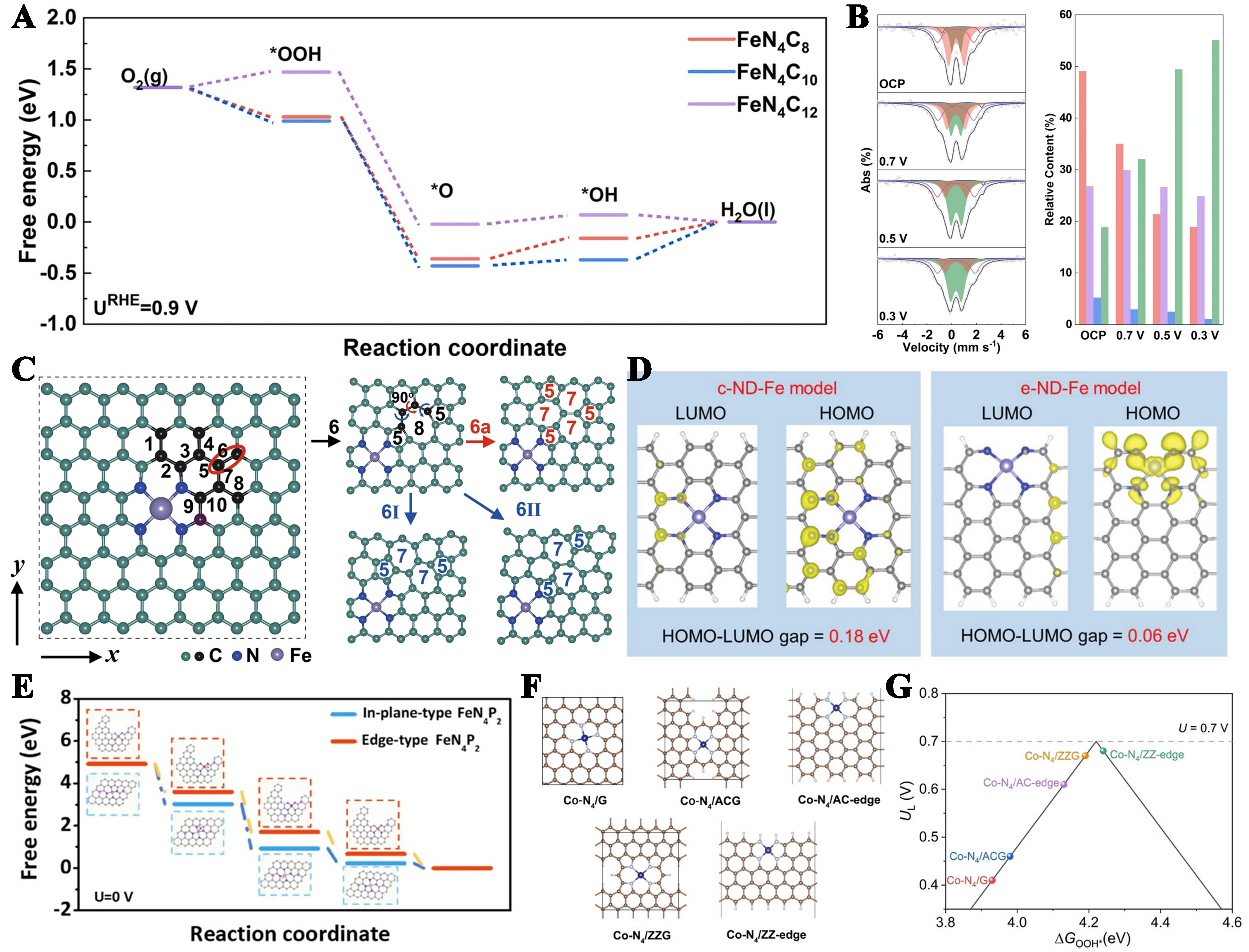
Figure 4. (A) The free energy diagram of typical ORR pathway of various FeN4 sites; (B) Fe-N-C in-situ Mössbauer spectra and the relative content of different types of FeN4. This figure is quoted with permission from Xu et al.[113]; (C) Optimized structure of a perfect FeN4 site and Divacancy defect models 6, 6a, 6I, and 6II. This figure is quoted with permission from Liu et al.[115]; (D) Molecular orbital distributions showing the HOMO and LUMO for c-ND-Fe and e-ND-Fe configurations. This figure is quoted with permission from Wang et al.[116]; (E) Calculated free energy diagrams for the ORR on in-plane-type FeN4P2 and edge-type FeN4P2 at zero electrode potential. This figure is quoted with permission from Yin et al.[117]; (F) The optimized structures of basal-plane Co-N4/G and edge-hosted Co-N4 configurations (brown: C; grey: N, blue: Co, and pink balls: H); (G) Computationally derived volcano plot for the 2e- ORR, illustrating the relationship between limiting potential (UL) and Gibbs free energy change for OOH* formation (ΔGOOH*). This figure is quoted with permission from Tian et al.[118]. ORR: Oxygen reduction reaction.


