

Life cycle carbon footprint of battery electric bus: coupling effects of mileage, energy mix and recycling processes
 0
0 Abstract
With the global push toward carbon neutrality, reducing greenhouse gas emissions in the transportation sector has become increasingly urgent. Electric buses represent a promising solution; however, their full life cycle carbon footprint remains underexplored. This study aims to address this gap by quantifying and comparing the life cycle carbon emissions of pure electric buses. A life cycle assessment (LCA) approach is applied to evaluate emissions across the production, usage, and recycling stages. Scenario analyses are conducted to assess the impact of carbon fiber reinforced polymer (CFRP) as a material substitute, variations in electricity generation mix, coal consumption rates, and the extent of recycled material utilization. Results show that buses using nickel manganese cobalt (NMC) battery type C have the lowest life cycle emissions at 55,814.89 kg CO2-eq, while those with lithium iron phosphate (LFP) battery type A have the highest, reaching 59,364.10 kg CO2-eq. During the production stage, the primary emission sources are the body, chassis, battery system, and electricity consumption. Substituting steel and aluminum with CFRP increases production emissions by up to 108.6%. However, in the operational phase, CFRP significantly reduces bus weight by 41.99% and cuts operational carbon emissions by 36.49%. In the recycling stage, NMC battery type C yields the highest emission reduction, achieving 14,943.86 kg CO2-eq, mainly due to the recovery of nickel and lithium compounds. These findings offer valuable insights for optimizing material choices, energy structures, and recycling strategies to support the low-carbon development of electric buses.
Keywords
INTRODUCTION
With accelerating urbanization in China, the number of automobiles is steadily increasing, contributing both to economic growth and to environmental concerns[1]. While the surge in vehicle use meets rising mobility demands, it also exerts significant negative impacts on the environment[2]. These include deteriorating urban air quality, the intensification of the greenhouse effect, and substantial petroleum consumption in China and globally[3]. According to statistics, the transportation sector is a major contributor to greenhouse gas (GHG) emissions, accounting for over 20% of global energy-related emissions[4]. To advance a more sustainable transportation system, China has placed growing emphasis on green and low-carbon development strategies[5]. Efforts are underway to diversify automotive energy sources and promote cleaner alternatives, positioning the low-carbon economy as a core driver of China’s development and recovery[6,7]. Against this backdrop, the new energy vehicle market with advantages such as energy conservation, emissions reduction, and environmental protection holds significant promise. It is seen as a core pillar in reducing reliance on fossil fuels and represents the future direction of the automotive industry[8,9]. Among various transportation modes, urban public buses form the backbone of public transit systems and play a crucial role in reducing per capita carbon emissions and alleviating urban air pollution. Given their large-scale deployment and central role in urban mobility, this study specifically focuses on battery-electric urban buses powered by lithium-ion batteries, which are widely adopted in China’s public transport network.
Electricity, as an alternative energy carrier for vehicles, enables the replacement of fossil fuels used in internal combustion engine vehicles (ICEVs) with renewable energy sources, thus significantly reducing CO2 emissions in the transport sector[10-12]. Consequently, the lifecycle carbon emissions of battery electric vehicles (BEVs) have become a key research focus. Among all components, rechargeable batteries are central to the shift toward sustainable, zero-emission transportation powered by renewable energy[13-15]. Lithium-ion batteries (LIBs), in particular, are widely adopted in electric vehicles (EVs) due to their high energy density, long cycle life, and cost-effectiveness compared to earlier technologies[16]. China has established a robust power battery industry centered around LiNixCoyMnzO2 (NCM) and lithium iron phosphate (LFP) battery chemistries, leading global advancements in this sector[17]. In 2021, these batteries accounted for 51.7% and 48.1% of the total installed power battery capacity in China, respectively. Their dominance in production and sales continued into 2022, surpassing all other battery types. Due to their technological maturity, safety, and cost advantages, LFP and NCM batteries have become the mainstream choices for electric buses in China’s public transit systems. Degen et al. reported that LFP and NMC900 batteries exhibit relatively low global warming potential (GWP) during the production phase-approximately 37 kg CO2-eq/kWh and 44 kg CO2-eq/kWh, respectively. Moreover, targeted recycling strategies can further reduce their environmental footprint, with GWP reductions of up to 38% achievable through improved manufacturing and recycling processes[18].
To achieve carbon peak and neutrality goals, China is vigorously promoting public transportation, particularly urban bus systems. Due to their high passenger capacity, fixed routes, and centralized management, buses are well suited for early, large-scale electrification and are a key focus for decarbonizing urban transport. However, the carbon footprint of electric buses is influenced by multiple factors, including powertrain type, driving speed, and battery composition. Li et al. conducted a comparative analysis of the life cycle energy consumption and emissions of urban buses using the Greenhouse gases, Regulated Emissions, and Energy use in Technologies (GREET) model, examining diesel, compressed natural gas (CNG), battery-electric, and hydrogen fuel cell vehicles[19]. Their results showed that CNG buses had the lowest energy consumption during fuel production, but the highest over the full life cycle. In contrast, battery-electric buses, despite requiring considerable energy during the production phase (second only to hydrogen fuel cell buses), had the lowest overall lifecycle energy consumption. Similarly, Pan et al. used the GREET model with diesel buses as a baseline to systematically evaluate the energy consumption intensity and GHG emissions of liquefied natural gas, hybrid electric, and battery-electric buses[20]. They concluded that under current conditions in China- characterized by a coal-dominated power mix and evolving battery technology - electric buses do not yet show clear life cycle energy or emissions advantages over diesel buses. However, with ongoing improvements in battery efficiency and a progressively cleaner electricity mix, the environmental benefits of electric buses are expected to become increasingly evident. Golkaram et al. (2024) quantified these benefits by applying electricity grid projections for 2030 and 2050, showing that the life cycle CO2 emissions of BEVs could be 50%-56% lower than those of ICEVs under future decarbonization scenarios[21]. Zhao et al. found that variations in hydrogen production pathways and electricity mixes significantly affect the life cycle CO2 emissions of electric buses, with fully renewable-powered systems achieving up to 89.6% reductions[22]. Ankathi et al. (2024), using a life cycle model tailored to Middle East and North Africa (MENA) countries, showed that BEVs only outperformed other powertrains in terms of well-to-wheel GHG emissions under future scenarios involving significantly reduced electricity transmission losses and substantially cleaner grids, albeit at high infrastructure costs. This highlights that BEVs are not inherently low-carbon under carbon-intensive electricity grids, and underscores the importance of accounting for local grid characteristics in national assessments, such as China’s[23]. Zhang et al. from Tsinghua University evaluated the effects of vehicle speed on CO2 emissions across various fuel types under different road conditions[24]. Their findings showed that CO2 emission rates increased with decreasing speed, with diesel buses showing the greatest increase, followed by natural gas and hybrid buses, indicating a varied sensitivity to speed across fuel types. Takahashi et al. developed a model incorporating real-world data from an electric bus equipped with lithium-ion batteries, combined with the Inventory Database for Environmental Analysis (IDEA) database and Life Cycle Assessment (LCA) methodology to calculate CO2 emissions[25]. The results showed that the carbon intensity of electricity is a dominant factor influencing emissions. In hybrid energy scenarios, 71.3% of total CO2 emissions occurred during the operation phase, while in renewable energy scenarios, 70.9% occurred during the material production stage. Additionally, battery degradation over six years increased hybrid bus emissions by 11.8%, while the use of renewable energy increased total emissions by only 3.9%.
Building on the above research, the present study focuses on lithium-ion battery electric buses-an increasingly important component of China’s public transportation electrification strategy-and develops a comprehensive carbon footprint evaluation framework that incorporates the production, operation, and recycling stages. While previous studies have addressed individual aspects, few provide an integrated assessment that simultaneously considers material substitution, electricity mix transitions, and recycling processes. This study aims to fill that gap by: (1) calculating changes in mass and carbon intensity when using lightweight materials (e.g., composites) in place of traditional materials such as steel and aluminum during the production stage; (2) constructing electricity mix scenarios based on China’s current and projected grid structure to evaluate how clean electricity, hydrogen production methods, driving range, and vehicle lightweighting influence life cycle CO2 emissions during operation; (3) exploring the role of key materials - such as nickel, manganese, cobalt, lithium, and carbon fiber composites - in reducing CO2 emissions during the recycling phase. By coupling these three stages within a unified modeling framework, this study provides a comprehensive and up-to-date life cycle carbon footprint assessment. The findings provide novel insights into how integrated technological pathways shape the environmental performance of electric buses and are expected to inform the development of more targeted and effective low-carbon strategies for China’s urban transit systems in pursuit of carbon neutrality.
RESEARCH METHODS AND EXPERIMENTAL DATA
Life cycle assessment
LCA, which has been evolving since the 1960s, is a widely recognized and essential tool in environmental management. It enables both quantitative and qualitative analyses of a product’s environmental impacts throughout its entire life cycle - from raw material extraction and manufacturing to usage and end-of-life disposal (i.e., cradle to grave). By compiling input-output inventories and interpreting the results according to the research objectives, LCA evaluates the potential environmental, economic, and social impacts of each stage[26,27]. This study follows the ISO 14040 and ISO 14044 standards for LCA, using background process data from the Ecoinvent v3 database, a comprehensive and internationally recognized inventory of industrial processes..
In this study, carbon footprint-defined as life cycle greenhouse gas emissions expressed in CO2-equivalent terms-is selected as the primary environmental impact indicator. The focus aligns with the study’s objective of supporting carbon neutrality and climate mitigation, especially in the context of China’s “dual carbon” goals. Assessing the carbon footprint enables a direct, policy-relevant evaluation of emission reduction potential across different battery technologies and energy grid scenarios. While other environmental indicators such as resource depletion, toxicity, and water usage are also important, they fall outside the scope of this analysis and will be considered in future research for a more comprehensive environmental assessment.
Research objectives
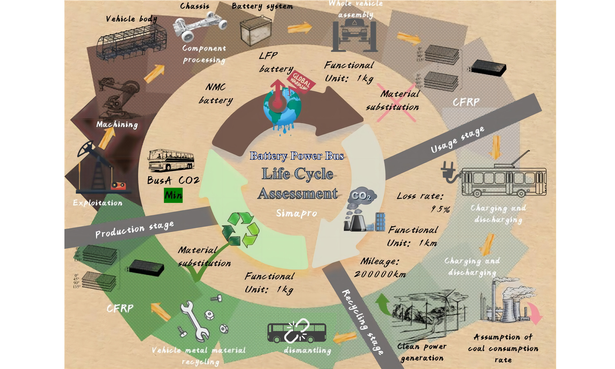
To support the goal of peaking CO2 emissions before 2030, EVs are being increasingly adopted in the transportation sector. In public transportation, large buses, typically around 12 meters in length, are commonly used. However, limited research exists on the life cycle carbon footprint of these vehicles from cradle to grave. This study employs the LCA method to establish a comprehensive lifecycle evaluation model for 12-meter electric buses currently available on the market. It examines total carbon emissions throughout the vehicle’s lifecycle and explores how energy source cleanliness and material recycling influence the potential to achieve carbon neutrality. To better illustrate the energy flow and structural composition of the pure electric bus under consideration, Figure 1 presents a typical configuration of a 12-meter electric bus, including key components such as the power battery, drive motor, motor control system, and auxiliary subsystems like air conditioning and lighting. These elements are incorporated into the life cycle inventory modeling using SimaPro software. The directional energy flow highlights the functional coupling between the battery system and various subsystems.
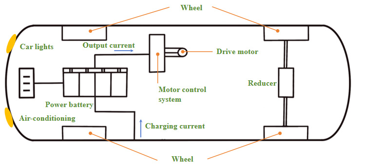
Figure 1. Main structure diagram of a pure electric bus.
The technical parameters summarized in Table 1 are based on data from Beijing Automotive Company and reflect the actual specifications of a 12-meter electric bus widely adopted in China’s public transport fleet. This information forms the basis for constructing a realistic lifecycle inventory model. The primary power sources for electric buses are currently lithium-ion battery packs - LFP and nickel manganese cobalt (NMC) batteries. LFP batteries have the advantages of good stability, long lifespan, and low cost that NMC batteries cannot fully match. They are particularly suitable for environments with extreme temperatures or where vehicle weight is less of a concern, making them ideal for addressing urban environmental challenges[28,29]. NMC batteries, in contrast, have higher energy density and lower weight. With advancements in battery protection systems and improved safety, they play an important role in improving the endurance of EVs[30]. This study includes one LFP and four NMC batteries (with different nickel, manganese, and cobalt molar ratios) to comprehensively analyze their carbon reduction potential, offering quantitative insights into their contributions to carbon neutrality in public transit.
Main parameters of three electric bus models
| Parameter | Electric bus |
| Energy consumption per 100 km | 80kWh |
| Dimensions (length × width × height) | 12,000 × 2550 × 3570 mm |
| Maximum power | 170 kW |
| Power battery type | LFP & NMC |
| Battery capacity | 400 Ah |
| Range | 300 km |
| Energy density (kg·L-1) | - |
Functional units
A core element of LCA is the selection of appropriate functional units (FUs) - standardized measures that ensure comparability and consistency in analyzing the research object and process[31]. The choice of FU directly influences the final evaluation results[32]. Therefore, careful consideration is given to defining FUs based on the specific stages and objectives of the research. For the production and recycling stages, this study adopts 1 kg as the functional unit. Since most vehicle components (excluding batteries) do not have capacity-related metrics, using kWh would be appropriate in this context. For the usage phase, the functional unit is defined as 1km driven on Chinese highways. Based on common usage mileage and vehicle retirement practices, this study assumes a total driving distance of 200,000 km for the entire life cycle of the BEV[33,34]. Battery replacement or other major component changes during operation are not considered in the baseline model, simplifying the analysis. However, the impact of such assumptions, particularly battery degradation over time, will be addressed in the sensitivity analysis to evaluate its effect on the overall findings.
Research methods
This study employs SimaPro software (version 9.4.0.2) to develop a comprehensive framework for carbon footprint assessment. A comparative life cycle analysis is conducted for battery electric buses, hydrogen fuel cell buses, and conventional diesel buses to evaluate their potential for achieving carbon neutrality. Key factors influencing carbon reduction are also examined, including the substitution of traditional materials with lightweight alternatives, changes in electricity mix and coal consumption scenarios, hydrogen production pathways, material recycling processes, and the application of carbon capture and storage technologies.
The model incorporates detailed input data, including the complete bill of materials for electric bus components, energy consumption figures, battery system configurations, and end-of-life recycling scenarios. Life cycle inventory data are primarily sourced from the Ecoinvent v3 database. The primary outputs of the model are GHG emissions across different life cycle stages and scenarios, enabling a comparative analysis of carbon footprints.
The system boundary of this study covers the entire life cycle of electric buses, including the production and manufacturing stage, the operation and use stage, and the recycling and treatment stage, as shown in Figure 2, which shows the LCA Boundary Scope of this research.
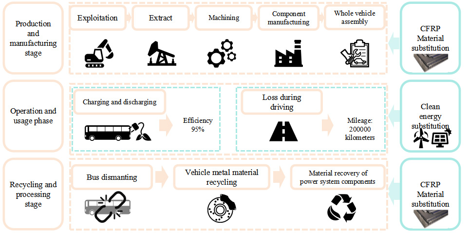
Figure 2. Life cycle assessment for battery-electric buses: Boundary Scope of the Study.
Production stage
The production stage includes the mining, extraction, and processing of raw materials, component manufacturing, and vehicle assembly. The transportation of raw materials and components between facilities is excluded from the system boundary. This exclusion is justified because the primary goal is to compare the relative environmental impacts of different battery technologies and future energy grid scenarios, rather than calculating the absolute carbon footprint of a specific supply chain. Transportation logistics are assumed to be similar across all vehicle types and thus are unlikely to significantly affect comparative results. Processes with high embodied emissions, such as aluminum production, are fully included using cradle-to-gate data from the Ecoinvent v3 database, which covers mining, refining, and upstream transport. The material composition of the bus body, chassis, and fluids is based on the research by Liu et al.[35]. Upstream material extraction and processing data are also sourced from Ecoinvent v3 to maintain consistency in background data. The bus body includes components such as the shell, doors, windows, front bumper, interior and exterior trim, seating, and systems for ventilation, heating, cooling, and air conditioning. The chassis comprises the transmission, driving, steering, and braking systems. It serves to house the engine and various assemblies, form the vehicle’s structural shape, transmit engine power, and ensure operational performance. The fluids include lubricating oil, brake fluid, wiper fluid, coolant, adhesives, and others. Full details of these components are provided in Supplementary Tables 1-3.
The power system consists of a power battery, a drive motor, and a balancing device. The bus is powered by a 170 kW AC permanent magnet synchronous motor, which receives electricity from the battery and converts it into mechanical energy to drive the wheels directly or through a transmission system. The composition[36] and mass fractions of the motor components are shown in Table 2, with a detailed list of balancing devices found in Supplementary Table 4.
Composition and mass proportion of the drive motor
| Component name | Material | Mass fraction (%) | Weight (kg) |
| Stator winding | Copper wire | 16.45 | 99.98 |
| Core | Silicon steel | 21.66 | 131.65 |
| Motor shaft | Steel | 9.76 | 59.32 |
| Permanent magnet rotor | NdFeB | 13. 11 | 79.68 |
| Motor housing | Aluminum alloy | 24.29 | 147.63 |
| Motor base | Aluminum alloy | 14.73 | 89.53 |
| Total mass (kg) | - | 100 | 607.8 |
The LFP battery system (referred to as N5) consists of a 1P22S module configuration (1 cell in parallel and 22 in series), a Battery Disconnect Unit (BDU), and other essential components. The BDU plays a critical role in managing the charging and discharging processes of EVs and affects battery life, control strategies, and high-voltage safety. The NMC battery system (designated N6) is composed of a BDU and two additional modules. Each module includes individual battery cells, fixing brackets, busbars, end plates, etc. Module-level data were sourced from Beijing Automotive Company. Detailed information on both N5 and N6 is provided in Supplementary Tables 5 and 6.
Figure 3 illustrates the system boundaries for the lithium-ion battery in both the module-based N5 configuration and the cell-to-pack N6 structure. The N5 system uses large modules comprising 132 LFP cells (Cell A), while the N6 system integrates components directly into the pack, consisting of 108 ternary cells with varying ratios of nickel, manganese, and cobalt (Cells B, C, D, and E). The material composition of each cell type is detailed in Table 3.
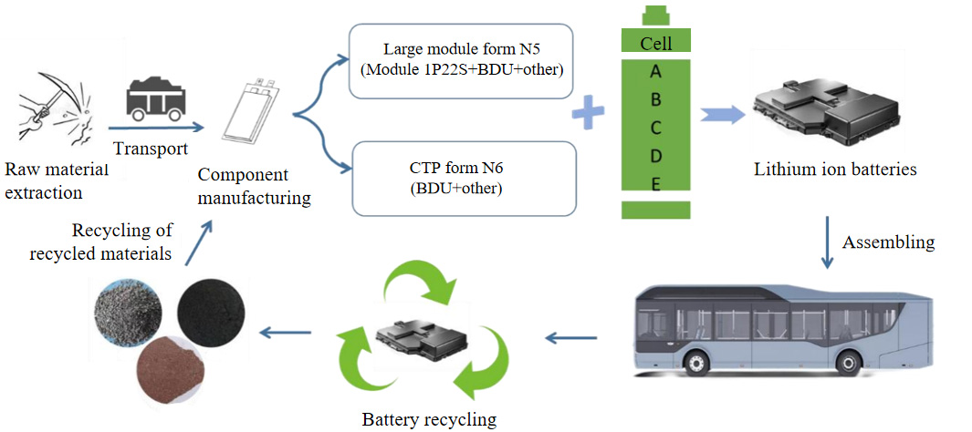
Figure 3. System boundary of lithium-ion batteries.
Cell Material Consumption (kg/cell)
| Cell code | Ni | Co | Mn | LiFePO4 | Li2CO3 | LiOH | Cu | Al | Electrolyte | Cell mass (kg) |
| A B C D E | - | - | - | 0.91 | - | - | 0.18 | 0.27 | 0.45 | 2065.71 |
| 0.30 | 0.04 | 0.02 | - | - | 0.28 | 0.19 | 0.41 | 0.32 | 1609.54 | |
| 0.53 | 0.06 | 0.21 | - | - | 0.62 | 0.39 | 0.80 | 0.65 | 1284. 12 | |
| 0.36 | 0.04 | 0.15 | - | - | 0.43 | 0.25 | 0.58 | 0.44 | 1505.73 | |
| 0.29 | 0.05 | 0.18 | - | 0.36 | 0.00 | 0.28 | 0.57 | 0.40 | 1607.82 |
Based on the above data, the total mass of the pure electric buses can be calculated, as shown in Table 4. Details of the vehicle assembly[37,38] inventories are provided in Supplementary Tables 7-10.
Total mass of pure electric buses by cell type (kg)
| Category | Composition | A | B | C | D | E |
| Vehicle body | Body, trim, accessories, electronics | 4,950 | 4,950 | 4,950 | 4,950 | 4,950 |
| Chassis | Powertrain, suspension, brakes, steering systems | 3,913.69 | 3,913.69 | 3,913.69 | 3,913.69 | 3,913.69 |
| Liquids | Brake fluid, coolant, adhesives, wiper fluid, lubricants | 175 | 175 | 175 | 175 | 175 |
| Power battery | As per cell configuration | 2,065.71 | 1,609.54 | 1,284. 12 | 1,505.73 | 1,607.82 |
| Dynamic system | Drive motor Balancing device | 607.8 964 | 607.8 964 | 607.8 964 | 607.8 964 | 607.8 964 |
| Total (kg) | - | 12,676.2 | 12,220.03 | 11,894.61 | 12,116.22 | 12,218.31 |
Usage phase
The usage phase refers to the operational stage during which an electric bus is driven on the road using electric power. The total mileage covered during this stage corresponds to the service-life mileage previously defined for the electric bus. This phase accounts for both the energy loss due to battery charging inefficiencies and the electricity consumed during vehicle operation. In this study, the charging and discharging efficiency of the battery is set at 95%[39]. A single charge-discharge cycle is assumed, and battery capacity degradation over time is not considered.
The power loss due to battery charging inefficiency, denoted as ELcd is calculated as:
where: ELcd -- Power loss due to charging inefficiency (kWh); Ds -- Driving range of the electric bus (km); ELper -- Electricity consumption per kilometer (kWh/km); ηcd -- Battery charging/discharging efficiency (%).
The electrical energy consumed during the battery pack’s usage phase, denoted as Eu, is calculated as:
where: Cb -- Battery pack capacity (kWh); Dc -- Driving range per charge (km/charge); Eu-- Total electricity consumed during usage (kWh).
Since electricity generation is not a zero-carbon process, EVs inevitably generate carbon emissions during operation. Therefore, the carbon footprint of electric buses during the usage phase is largely determined by the carbon intensity of the power generation mix. As of 2022, China’s power generation remains dominated by thermal power, primarily from coal, followed by hydropower. Hydropower and natural gas contribute similarly, while nuclear and solar power also play comparable roles. China is actively working to transition to a clean, low-carbon, safe, and efficient energy system. The 2022 power generation structure is shown in Figure 4 (data from the National Bureau of Statistics).
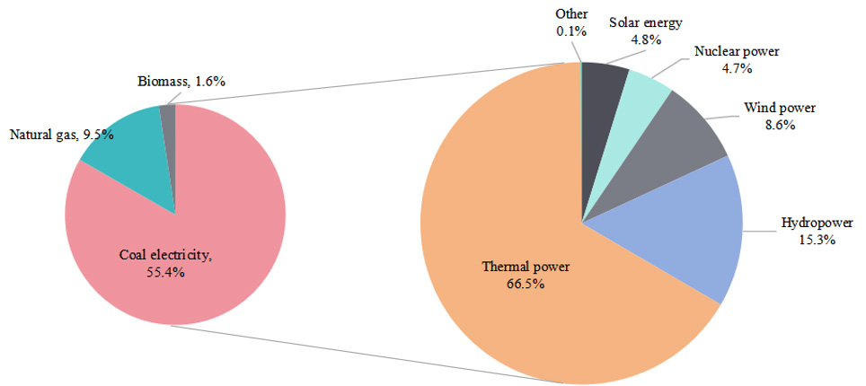
Figure 4. China’s power generation structure in 2022.
The cleanliness of electricity, i.e., its degree of decarbonization, has a significant impact on the environmental sustainability of electric buses. Measures to improve electricity cleanliness include:
(1) Clean and efficient use of coal (carbon reduction): In China, most thermal electricity is generated from coal, with minor contributions from oil, natural gas, coal gangue, biomass, and waste. Therefore, coal remains the key focus in improving thermal power efficiency. Strategies for reducing carbon emissions from coal-fired power generation include:
Reducing coal consumption rate. Coal consumption rate refers to the amount of fuel consumed per unit of electricity output, typically expressed in g/kWh. In 2022, the national average was about 435.7g/kWh, while the Huaneng Qinmei Ruijin Phase II project achieved a significantly lower rate of 249.7g/kWh (rounded to 250 g/kWh). Different scenarios are considered:
Scenario 1 - Medium temperature/pressure condensing power plant (480 g/kWh);
Scenario 2 - High temperature/pressure power plant (380 g/kWh);
Scenario 3 - Ultra-high pressure power plant (360 g/kWh);
Scenario 4 - Cogeneration plant (280 g/kWh);
Scenario 5 - Huaneng Phase II project (250 g/kWh);
Scenario 6 - future projection (200 g/kWh).
Calculation of carbon emissions from electricity:
where: ECO2--CO2 emissions from coal combustion (tCO2); FC--Coal consumption (t); NCV--Net calorific value of coal (GJ/t); EF--CO2 emission factor (tCO2/GJ).
The emission factor EF is further calculated as:
where: CC--Carbon content per unit calorific value (tCO2/GJ); OF--Carbon oxidation rate (%); 44/12 --Molecular weight ratio of CO2 to carbon.
Pollutant reduction via CCS. Carbon Capture and Storage (CCS) technologies can capture CO2 emissions from power plants and process them through desulfurization and other methods, significantly reducing carbon output[40].
(2) Clean electricity mix (energy structure optimization): This approach focuses on decreasing the share of high-carbon electricity sources such as coal, and promoting low-carbon renewable sources such as solar and wind energy. Based on expert predictions and authoritative reports, 11 scenario models are developed to assess the green transformation potential of China’s transportation industry under different power generation mixes. Scenario descriptions are as follows:
Basic scenario: Actual 2022 power generation structure; serves as a reference for future comparisons.
Scenario 1: 2030 Clean Nuclear Energy Development Assumption;
Scenario 2: 2030 Green Renewable Energy Development Assumption;
Scenario 3: 2050 clean nuclear energy development assumption;
Scenario 4: 2050 green and renewable energy development assumption;
Scenario 5: By 2030, non-fossil energy accounts for 25%of primary energy and 46.7% of electricity generation. (based on projections by Zhou Xiaoxin, CAS academician);
Scenario 6: By 2050, non-fossil energy reaches 59% of consumption and 73.8% of electricity generation;
Scenario 7: By 2060, non-fossil energy reaches 89% of consumption and 92.7% of electricity generation;
Scenario 8: By 2030, the non-fossil energy share in the power industry reaches 44.8% (based on the Electric Power Supply Structure Transformation (EPSST) model by Liu et al., Zhejiang University[41]);
Scenario 9: Non-fossil share reaches 78% by 2030;
Scenario 10: Non-fossil share reaches 87.53% by 2030.
All hypothetical scenarios for power generation structures are shown in Table 5.
Power generation structure scenario assumptions
| Scenario | Hydropower | Wind power | Nuclear power | Solar energy | Coal | Natural gas | Biomass | Petroleum |
| Basic | 15.28 % | 8.62 % | 4.72 % | 4.83 % | 55.44 % | 9.50 % | 1.61 % | - |
| Scenario 1 | 18.60 % | 11.00 % | 7.40 % | 11.40 % | 40.00 % | 9.00 % | 1.60 % | 1.00 % |
| Scenario 2 | 18.60 % | 12.00 % | 4.39 % | 13.40 % | 40.00 % | 9.00 % | 1.60 % | 1.00 % |
| Scenario 3 | 15.60 % | 19.00 % | 31.30 % | 14.00 % | 13.00 % | 5.50 % | 1.60 % | - |
| Scenario4 | 15.60 % | 26.00 % | 11.20 % | 23.10 % | 14.00 % | 8.50 % | 1.60 % | - |
| Scenario 5 | 16.00 % | 11.00 % | 7.00 % | 11.00 % | 44.00 % | 9.00 % | 2.00 % | - |
| Scenario 6 | 14.00 % | 19.00 % | 12.00 % | 24.00 % | 13.00 % | 13.00 % | 5.00 % | - |
| Scenario 7 | 12.50 % | 27.00 % | 12.80 % | 33.70 % | 1.50 % | 5.80 % | 6.70 % | - |
| Scenario 8 | 15.70 % | 10.32 % | 5.28 % | 13.50 % | 53.78 % | 1.42 % | - | - |
| Scenario 9 | 16.19 % | 24.61 % | 4.95 % | 32.40 % | 18.43 % | 3.42 % | - | - |
| Scenario 10 | 16.60 % | 30.15 % | 4.45 % | 31.84 % | 7.97 % | 4.50 % | - | - |
Recycling stage
To address the scrapping and recycling of automobiles, China issued the Technical Policy for Automobile Product Recycling and Utilization to guide enterprises in optimizing vehicle design for easier dismantling, reuse, and recycling[42]. The policy aims to enhance recycling efficiency, reduce resource waste, and ensure a smooth and effective recycling process. Accordingly, this study defines the recycling stage to include vehicle dismantling, recovery of metal and lightweight structural materials, and recycling of batteries and power system components. However, due to the underdeveloped secondary utilization market for batteries and an incomplete industrial chain, cascading utilization of key components is not considered. Additionally, the construction and spatial distribution of power infrastructure (such as gas stations, charging stations, and hydrogen refueling stations) are not included within the study scope.
Given the inevitable wear, corrosion, and fluid losses during vehicle use, this study assumes that the mass of recycled vehicles is 98% of their original weight. This 98% recovery rate assumption is supported by a Monte Carlo sensitivity analysis, which demonstrates that the results remain robust across a reasonable range of recycling efficiency scenarios. For vehicle bodies, chassis, and structural components, only metal recycling is considered. Data on recycling efficiency and associated energy consumption are primarily sourced from the Ecoinvent v3 database and supplemented with literature-based estimates[43-45], as detailed in the Supplementary Table 11.
Recycling and reusing carbon fiber reinforced polymer (CFRP) waste is essential for sustainable production and cost reduction of CFRP products. Supercritical fluid technology is employed for this purpose, with details provided in Supplementary Table 12.
Battery recycling is modeled in greater detail, given its critical importance for environmental performance. LFP (LiFePO4) and NMC batteries use different recycling techniques due to their differing compositions. Waste LiFePO4 batteries contain valuable recoverable materials such as Li, Al, Cu, graphite, and Fe[46]. Part of the recycling process list used in this study is based on the research by Wang Zhuopu from Tsinghua University[47], which includes both traditional wet-process technologies and complete “physical method” recovery techniques. The recovered products include copper foil, aluminum foil, and LFP cathode active materials. Furthermore, based on research by Liu et al., this study incorporates a mechanochemical oxidation method using NaClO as a solid oxidant to recover LFP cathode materials, offering advantages such as fast reaction and low solvent consumption[48-50]. Detailed process lists are provided in the Supplementary Table 13.
For NMC batteries, the positive electrodes contain highly valuable heavy metal elements such as nickel, manganese, and cobalt, making them a significant resource. Efficient recycling and regeneration of NMC battery materials can reduce environmental pollution and alleviate the pressure of nickel, cobalt, and lithium resource shortage[51]. This study draws partly from Xie Yinghao’s research on directional circulation process for waste power batteries, which combines the advantages of traditional wet and pyrometallurgical methods to effectively recover aluminum and copper[52]. Additionally, Li Kang’s research at Beijing University of Chemical Technology is referenced for using natural tea polyphenols as reducing agents in wet leaching processes, thereby reducing acid consumption during the leaching of waste NMC cathode materials[53]. The corresponding recycling details are provided in Supplementary Table 14.
For various NMC chemistries (types B, C, D, and E), the required amount of sulfuric acid for leaching varies according to the metal molar ratios. Based on Jiang et al.’s methodology, the acid input per kg of battery is assumed to be 1.75 kg, 3.44 kg, 2.1 kg, and 2.04 kg, respectively[54]. This comprehensive modeling of recycling processes captures key differences in material recovery potential across different vehicle and battery types, enabling a more robust assessment of end-of-life emissions and resource savings.
DATA ANALYSIS
Carbon emission potential during the production stage of assembling LFP and NMC battery buses
Carbon emissions from LFP and NMC battery systems
The carbon footprint of individual battery cells A, B, C, D, and E is 13.50, 16.45, 31.78, 22.29, and 19.61 kg CO2 eq, respectively. Among these, cell A has the lowest carbon footprint, while cell C has the highest. However, due to differences in the masses of the individual cells, directly comparing their total emissions may be misleading. To allow for meaningful comparison across cell types, the total carbon emissions of each cell were normalized by its mass, yielding a per-unit-mass carbon footprint, as shown in Table 6. This normalization provides a more objective evaluation of the environmental performance of each battery chemistry.
Carbon footprint per unit mass of cell (kg CO2 eq)
| Cell type Component | Cell A | Cell B | Cell C | Cell D | Cell E |
| Ni | - | 2.31 | 1.93 | 1.90 | 1.48 |
| Co | - | 0.26 | 0.18 | 0.18 | 0.21 |
| Mn | - | 0.04 | 0.18 | 0.19 | 0.22 |
| LiFePO4 | 2.58 | - | - | - | - |
| Li2CO3 | - | - | - | - | 0.30 |
| LiOH | - | 0.94 | 0.98 | 0.99 | - |
| Cu | 0.37 | 0.51 | 0.49 | 0.46 | 0.49 |
| Al | 2.31 | 4.67 | 4.15 | 4.38 | 4. 14 |
| Electrolyte | 0.74 | 0.67 | 0.65 | 0.64 | 0.56 |
| Total | 6.00 | 9.40 | 8.57 | 8.74 | 7.40 |
Table 6 shows the carbon footprint per 1kg of battery cell. The carbon footprints for producing 1kg of LFP (A) and NMC cells (B: ternary 8-series, C and D: ternary 6-series, E: ternary 5-series) are 6.00, 9.40, 8.57, 8.74, and 7.40 kg CO2 eq, respectively. Among them, LFP cell A has the lowest emissions, while ternary cell B has the highest. Compared to LFP, the carbon footprint of the NMC cells is higher by 56.67%, 42.83%, 45.67%, and 23.33%, respectively. This indicates that, for the same material input of 1 kg, NMC battery cells generate more carbon emissions. This difference may be attributed to the higher emission factors of the raw materials used in NMC batteries, such as nickel-, manganese-, and cobalt-based compounds. Notably, the carbon footprints of NMC cells also vary depending on the molar ratios of these metals. Cell E (ternary 5-series) has the lowest carbon footprint among the NMC types, and the carbon footprint increases with the nickel content. Therefore, although high-nickel batteries offer high energy density and longer EV driving range, they also pose greater environmental burdens due to increased carbon emissions.
In LFP cells, lithium iron phosphate contributes the most to carbon emissions (43%), followed by aluminum (38.5%). Together, they account for over 80% of the carbon footprint of cell A. In ternary (NMC) cells, aluminum and nickel are the main contributors. The significant environmental impact of aluminum may be due to the high carbon emissions from thermal power used in upstream aluminum production. For example, producing one ton of aluminum using thermal power emits approximately 11.2 tons of CO2. In contrast, aluminum produced using hydropower generates negligible emissions, although in 2020, only 10% of electrolytic aluminum was sourced this way.
For battery systems excluding the cells, the top five CO2 emission contributors in the N5 system are:
Carbon emissions during the production phase of LFP and NMC battery buses
To assess the production-phase emissions of electric buses using various battery systems, battery packs A-E were integrated into bus models, and carbon footprint indicators were used for evaluation. While the battery packs differed in energy density and mass, all had the same capacity. Other components (body, chassis, fluids, balance devices, and drive motors) were standardized in terms of composition and mass. Figure 5 illustrates the carbon emissions and emission reduction rates for the five battery systems during bus production.

Figure 5. Carbon emissions and reduction rates of five battery packs in electric bus production.
As shown in Figure 5, the bus with the highest CO2 emissions is equipped with the N5 battery system. The lowest emissions were observed for the bus equipped with the N6 battery system and cell C, at 55,814.89 kg CO2 eq, compared to 59,364.1 kg CO2 eq for the LFP-based Bus A. Buses B, C, D, and E achieved emission reductions of 0.56%, 5.98%, 2.8%, and 3.89%, respectively, compared to Bus A. Although LFP battery A has the lowest unit emissions per kg, its mass energy density is significantly lower than that of the four NMC batteries. As a result, for the same capacity, LFP batteries are heavier and generate more emissions overall. The compaction density of LFP ranges from 2.5-2.65 g/cm3, while that of ternary materials is 3.6-4.0 g/cm3. Higher compaction density allows more active material per unit volume, increasing the battery’s capacity. This is a key factor differentiating LFP and NMC technologies. For NMC batteries, cells B and C have similar energy densities and capacities, so their masses should be approximately the same. However, discrepancies still exist due to differences in cell design. Battery packs are built by connecting multiple cells in series and parallel, along with structural components for current collection, data acquisition, and protection, resulting in large modules. Variations in the positive electrode material ratios further influence the total carbon footprint during production.
Figure 6 presents the proportion of emissions from different parts of the production process for buses with various batteries. The main sources of CO2 emissions are the body, chassis, battery system, and electrical energy used in production. Reducing electricity consumption or switching to cleaner energy sources during manufacturing can effectively reduce total emissions. In body manufacturing, steel, PET, and aluminum account for 87.3% of emissions. In chassis manufacturing, steel, rubber, and aluminum make up 79.6%. For battery systems, the top contributors include steel, aluminum, silicone, and PET. These materials are associated with significant emissions during their extraction and processing. Overall, traditional materials such as steel and aluminum dominate the carbon footprint across the entire vehicle manufacturing chain.

Figure 6. Emission contribution of each component in the production process.
Carbon emissions from different materials used in the production stage of pure electric buses
To explore the potential for emission reduction, CFRPs and other advanced materials are being considered as substitutes for traditional materials, mainly for the vehicle’s interior, body-in-white, and to a large extent, the chassis[55]. CFRP weighs only one-quarter as much as traditional steel, offers eight times the strength, and is 42% lighter than aluminum. In this study, we calculate carbon emissions to assess the carbon reduction potential of replacing steel and aluminum with CFRP in the manufacturing of car bodies and chassis.
As shown in Figure 7, using CFRP in body manufacturing results in a significantly higher carbon footprint - 292.46% greater than that of traditional steel and aluminum. Similar trends are observed in chassis and balancing device production, where CFRP increases carbon emissions by 173.93% and 46.41%, respectively, compared to traditional materials. This is likely due to the nature of CFRP as a composite material, made by impregnating carbon fibers with thermosetting resins- a process that is both energy- and emission-intensive[56]. Additionally, the production of carbon fiber itself is a high-emission, high-energy process. It involves using acrylonitrile, a petroleum-derived compound, which is spun and carbonized at temperatures exceeding 1000 °C. This contributes to the high carbon footprint of CFRP. Interestingly, when traditional materials are used, carbon emissions from chassis production are 24.65% higher than those from the body. However, when CFRP is used, this pattern reverses - the body generates more emissions than the chassis. This can be explained by the differing carbon footprints of aluminum and steel per unit mass. While the steel used in the body is about 1.23 times the amount used in the chassis, the aluminum used in the chassis is about 8 times greater than the steel content. Consequently, the chassis has a higher carbon footprint than the body when traditional materials are used. However, when CFRP replaces steel and aluminum, the relative weights change: when CFRP replaces steel or aluminum, the vehicle body becomes approximately 1.15 times heavier than the chassis. Given the high carbon emission intensity of CFRP, the carbon footprint of the CFRP-based body then exceeds that of the chassis.
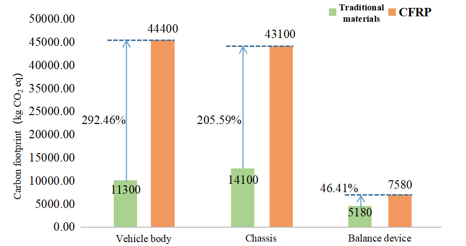
Figure 7. Comparison of carbon emissions from conventional and CFRP materials used in the manufacturing of the body, chassis and balancing devices. CFRP: Carbon fiber reinforced polymer.
As indicated in Table 7, during the production phase, lightweight materials like CFRP do not reduce carbon emissions - in fact, they may more than double CO2 emissions compared to traditional materials. The emission reduction potential of CFRP must be evaluated comprehensively, taking into account its performance over the entire vehicle life cycle, including the use and recycling phases.
Emission ratios of lightweight vs. traditional materials in electric bus production
| Material type | A | B | C | D | E |
| Traditional materials | 59364.10 | 59031.54 | 55814.89 | 57704.08 | 57057.19 |
| CFRP | 123854.93 | 123522.37 | 120305.71 | 122194.90 | 121548.02 |
| Increase (%) | 108.64% | 109.25% | 115.54% | 111.76% | 113.03% |
Analysis of carbon emission potential during the use stage of pure electric buses
Carbon emissions from pure electric buses with different material life cycle mileages
Driven by considerations of sustainability, cost, and performance, the trend toward automotive lightweighting has significantly increased the demand for lightweight materials. These materials are increasingly recognized as essential components of modern transportation systems and circular economy strategies. It is widely believed that even as the transportation industry shifts from ICEVs to EVs, lightweight will still be a key focus[57]. CFRP possesses excellent properties - such as low weight, high strength, impact resistance, and corrosion resistance - that make it especially suitable for reducing the overall mass of electric buses. This weight reduction helps offset the added mass from additional batteries compared to traditional buses, thereby improving energy efficiency during operation[58]. These characteristics suggest that CFRP will play a leading role in future lightweight vehicle body structures.
According to Czerwinski’s research, a 10% reduction in vehicle weight can increase the driving range of a pure electric vehicle by 13.7%[59]. As shown in Figure 8, the average carbon footprint of a traditional pure electric bus over its entire use phase is 133,424.78 kg CO2 eq. When CFRP is used instead of traditional materials, the vehicle’s total weight is reduced by an average of 41.99%. As a result, the carbon footprint drops significantly to 84,739.89 kg CO2 eq- a reduction of 48,684.89 kg of CO2 eq, or 36.49%. Therefore, the use of CFRP contributes substantially to lowering the operational carbon footprint of pure electric buses.
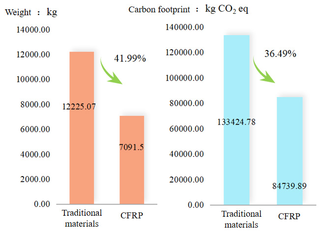
Figure 8. Comparison of traditional materials and CFRP for pure electric buses during the use stage. CFRP: Carbon fiber reinforced polymer.
Impact of electricity cleanliness on carbon footprint during the usage stage
EVs are widely recognized for their “zero emissions” during the usage stage. However, the electricity that powers them is not completely clean, especially in China, where the energy mix remains heavily dependent on coal. Electricity production in China still involves significant coal consumption, resulting in substantial carbon emissions and pollution. Therefore, this study employs forecasts from authoritative institutions and researchers regarding China’s future electricity mix to examine how advancements in the power structure for electric buses could promote environmentally sustainable public transport and achieve meaningful reductions in both carbon emissions and energy consumption.
As shown in Figure 9, under the 2022 baseline scenario, the carbon footprint of electric buses during operation is the highest. This is mainly because thermal power remains China’s dominant energy source, accounting for 66.5% of the electricity mix. Coal combustion, in particular, emits 1.285kg of CO2 per kWh, along with acid gases such as SO2 and NOx. Although hydropower accounts for 15.28% and is comparatively clean, it is insufficient to offset the dominance of coal-fired electricity.
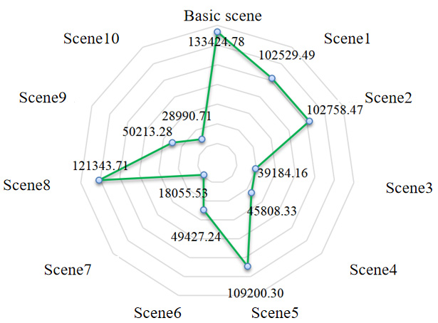
Figure 9. Carbon emissions simulated under 11 scenarios (Unit: kg CO2-eq).
In contrast, Scenario 7 results in the lowest carbon footprint during the operational stage, with emissions of 18,055.53 kg CO2-eq - just 13.5% of the baseline scenario - representing an 86.5% reduction. This scenario envisions the ideal 2060 energy mix, in which wind and photovoltaic sources contribute nearly two-thirds of total power generation. These renewable sources harness natural resources - wind and solar thermal energy - to produce electricity with zero emissions.
Other scenarios, such as Scenario 1 (102,529.49 kg CO2-eq) and Scenario 2 (102,758.47 kg CO2-eq), represent intermediate stages in grid decarbonization, showing moderate emission reductions relative to the baseline. Notably, Scenario 5, despite aligning with current policy goals, still results in relatively high emissions (109,200.30 kg CO2-eq), highlighting the need for more aggressive decarbonization pathways.
Due to the inherent intermittency of renewables, energy storage is gaining increasing importance. Pumped storage facilities act as stabilizers and regulators within the power system, enhancing the efficient use of wind and solar energy and minimizing curtailment. Their development is of great significance in increasing the proportion of “green electricity” and ensuring grid reliability. In Scenario 7, hydropower comprises 16.6% of the total electricity mix. A coordinated use of hydropower, wind, and PV generation is essential for maintaining a stable electricity supply in China.
As shown in Figure 10, analysis of Scenarios 1, 2, 5, and 8 for the year 2030 indicates that Scenario 1 has the lowest emissions, at just 76.84% of the baseline scenario, while Scenario 8 has the largest, at 90.95% - 1.18 times higher than Scenario 1. This difference stems from Scenario 8’s high share of coal power (53.78%) compared to 40% in Scenario 1, along with a lower share of hydropower, wind, and nuclear sources. These findings confirm that a higher coal share leads to increased emissions, while higher shares of nuclear and renewables reduce the carbon footprint. The only difference between Scenarios 1 and 2 lies in the proportions of wind, nuclear, and photovoltaic power - Scenario 1 has a slightly higher share of nuclear energy, suggesting its superior carbon reduction potential relative to wind and photovoltaic. Compared to Scenario 1, Scenario 5 has higher shares of coal and biomass and slightly lower shares of hydropower, nuclear, and photovoltaic, leading to a broader carbon footprint gap. Overall, reducing coal’s share and accelerating clean development remain the most effective emission reduction strategies.
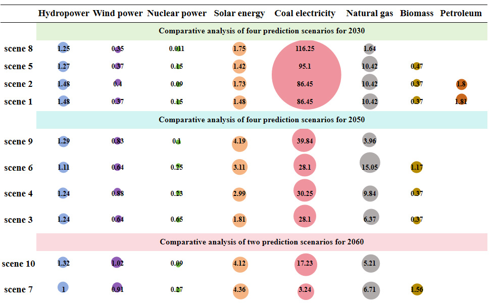
Figure 10. Comparative Analysis of Multiple Predictive Scenarios for 2030, 2050, and 2060 (Unit: × 103 kg CO2 eq).
An analysis of Scenarios 3, 4, 6, and 9 for the year 2050 shows that Scenario 3 has the lowest emissions at 39,184.16 kg CO2 eq, or 29.37% of the baseline. In contrast, Scenario 9 has the highest emissions (50,213.28 kg CO2 eq), which is 37.63% of the baseline and 1.28 times higher than Scenario 3. The carbon advantage of clean nuclear energy is evident, especially in scenarios where nuclear, wind, hydropower, and photovoltaic dominate. Nuclear power, which generates electricity through fission without releasing atmospheric pollutants, is notably cleaner than thermal generation. The comparison between Scenarios 3 and 4 mirrors that of Scenarios 1 and 2 in 2030, with a 6,624.71 kg CO2 eq reduction attributed to a nuclear share approaching one-third. Compared to Scenario 3, Scenario 6 has higher shares of photovoltaic, natural gas, and biomass generation, but lower shares of hydro and nuclear power, resulting in a carbon footprint 10,243.08 kg CO2 eq higher. Scenarios 6 and 9 have comparable total emissions, highlighting the trade-offs in different energy mixes. These findings underscore the importance of expanding clean nuclear energy to support green and sustainable development in China. However, safety concerns remain, given the history of nuclear accidents worldwide.
In 2060, Scenario 7 again yields the lowest emissions, only 18,055.53 kg CO2 eq, representing 13.53% of the baseline and an 86.5% reduction. Wind and photovoltaic collectively exceed 60% of the electricity mix, while coal falls to just 1.5%, signaling its near-complete phase-out. Scenario 10, while slightly less ideal, still achieves emissions of 28,990.71 kg CO2 eq (21.73% of the baseline), a 78.3% reduction. These projections suggest that by 2060, China’s clean energy share could approach 90%, and fossil fuels may be largely eliminated. A full transition to clean electricity would dramatically increase EVs’ environmental benefits and support the country’s carbon neutrality goals.
In addition to optimizing the energy mix and increasing clean energy adoption, improving coal-fired generation efficiency is another viable strategy. This study sets coal consumption rates in Scenarios 1-6 at 480g/kWh, 380g/kWh, 360g/kWh, 280g/kWh, 250g/kWh, and 200g/kWh, respectively.
As shown in Figure 11A and B, lower coal consumption rates lead to reduced CO2 emissions from coal-fired power. Except for Scenario 1, all scenarios show significant emission reductions when implemented nationwide. Compared with high-temperature, high-pressure power plants, the minimum reduction reaches 12.8%. Further technological improvements could lower emissions by up to 54.1%, as in Scenario 6. Scenario 5 represents the best coal efficiency achievable with current technology, reducing emissions by 42.6% relative to the 2022 national average. Similarly, the total carbon footprint for electric bus electricity during use follows this trend. In 2022, China’s average coal consumption is about 435g/kWh - between the levels of Scenarios 1 and 2 - and the corresponding footprint also falls between these values. If the technology in Scenario 5 is widely adopted, CO2 emissions could drop by 51,070.42 kg eq. Further reducing coal use by 50g/kWh could cut emissions by 64,820.77 kg CO2 eq, achieving a 48.6% reduction. Thus, effective emission reduction strategies include phasing out small thermal plants, enhancing combustion efficiency in large plants, and promoting supercritical and ultra-supercritical boiler technologies.
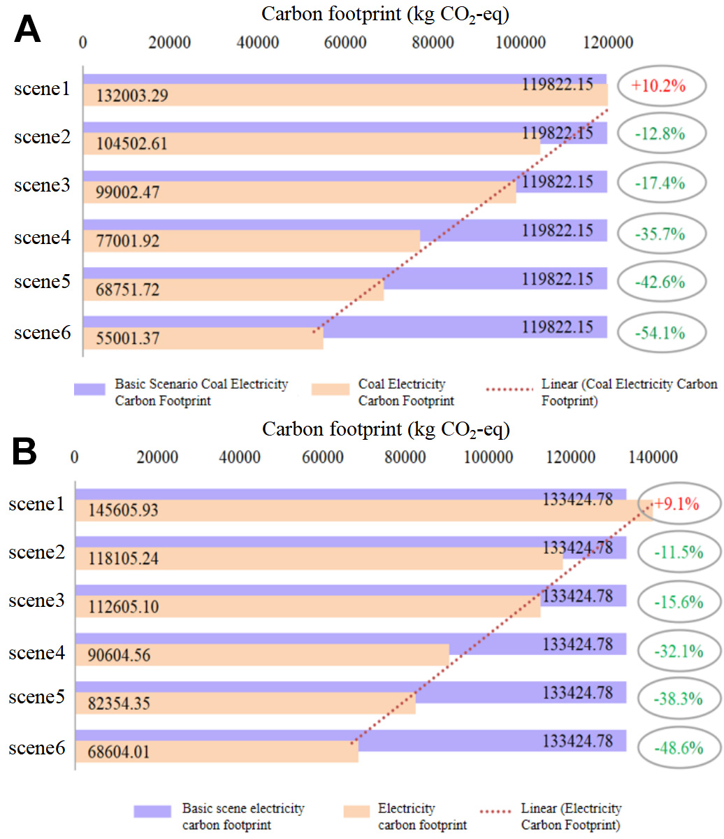
Figure 11. Comparison of power carbon footprints under different coal consumption rate scenarios during the use stage: (A) Carbon footprint of coal-fired power generation across scenarios; (B) Total electricity carbon footprint for EV operation. EV: Electric vehicle.
Carbon emission potential during the recycling phase of electric buses
Recycling processes and carbon emissions
Based on the recycling inventory, an analysis was conducted for the vehicle body, chassis, balancing device, power battery, and other components of electric buses. The results are presented below:
As shown in Figure 12, pure electric buses equipped with LFP batteries achieve carbon reductions throughout the recycling stage, with a total reduction of 6,557.72 kg CO2 eq, representing 11.05% of the emissions from the production stage. Specifically, the body, chassis, and balancing device were recycled for four key metals: steel, iron, aluminum, and copper. The carbon footprints of the recycling process for these components were 4,192.72, 3,695.25, and 1,001.17 kg CO2 eq, respectively, while the corresponding emission reductions from material recovery were 1,887.58, 5,757.67, and 3,110.99 kg CO2 eq. These figures highlight the substantial carbon reduction potential of recycling. However, in the case of LFP batteries, the carbon emissions from the recycling process exceed the emissions saved through material recovery. In other words, recycling LFP batteries alone does not necessarily result in net carbon savings - likely due to the limitations or inefficiencies in current recycling technologies.
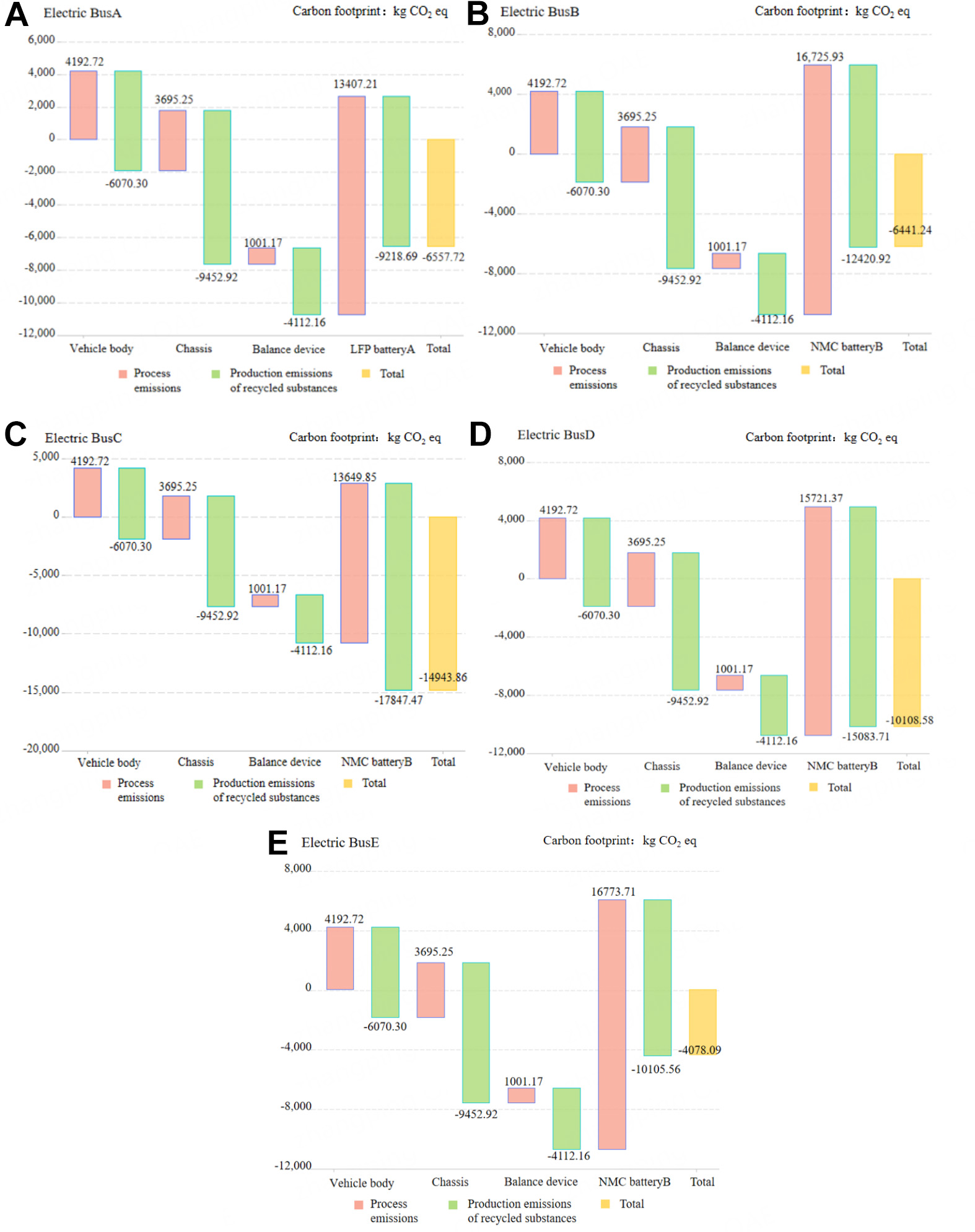
Figure 12. Carbon emission reduction from the recycling of pure electric buses.
Pure electric buses equipped with NMC batteries (B, C, D, and E) also show overall CO2 emission reductions during the recovery phase. However, the extent of reduction varies: 6,441.24, 14,943.86, 10,108.58, and 4,078.09 kg CO2 eq, accounting for 10.91%, 26.77%, 17.52%, and 7% of the emissions during the production phase, respectively. Since the body, chassis, and balancing device are consistent in composition and weight across vehicles, their recycling processes yield similar results and are not discussed further here. Focusing on battery recycling, the emissions reduction varies significantly among the four NMC batteries. For batteries B, D, and E, the emissions from recycling exceed the benefits, with net increases of 4,305.01, 637.66, and 6,668 kg CO2 eq, respectively. Only battery C demonstrates net CO2 savings, reducing emissions by 4,197.65 CO2 eq. The underlying reasons for this disparity are analyzed in the following section.
Analysis of emission contributions and reduction potential
As highlighted earlier, CO2 emission reductions during the recycling phase depend on factors such as the recycling process, battery type, and the proportion of components within each battery pack. Therefore, it is necessary to analyze the emission contributions of recycling processes and the production of recovered materials to understand the root causes of emissions.
As shown in Figure 13, during the recycling of Battery A, electricity and liquid nitrogen are the primary contributors to carbon emissions, accounting for 59.29% and 25.28%, respectively. This underscores the critical role of clean electricity throughout the battery life cycle - production, use, and recycling. To achieve sustainable development in the transportation sector, increasing the share of renewable energy in the power grid is essential. Additionally, optimizing the production process of liquid nitrogen to enhance its efficiency can help reduce emissions further. For batteries B, C, D, and E, the recycling process is similar, though the amount of reagents used varies due to differences in battery composition. Overall, the emissions pattern remains consistent. Tea polyphenols and alkaline substance NaOH - used in the acid-leaching reduction of NMC cathode materials - are the main sources of emissions, contributing 55.27% and 23.55%, respectively. Notably, ethanol and chloroform, heavily used in tea polyphenol production, contribute 63.82% and 35.96% of its carbon footprint. Therefore, to reduce emissions, both the production technologies for tea polyphenols and NaOH and their usage efficiency in recycling processes must be improved. For instance, optimizing the tea polyphenol extraction process - including refining temperature, time, and yield (currently 34.1%) - could enhance sustainability.
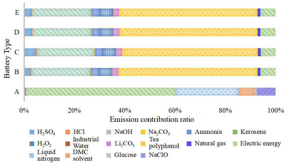
Figure 13. CO2 emission contributions in the recycling of 1 kg of used power battery.
Figure 14 reveals that LFP batteries yield five recycled materials: copper foil, aluminum foil, FePO4, Li2CO3, and sodium chloride. The emission reduction potential varies across these substances. Aluminum, FePO4, and copper show notable benefits. Aluminum, widely used in battery structures such as box frames and cooling plates, carries a large production carbon burden, making its recycling especially beneficial. FePO4 also has high production emissions due to its use of phosphoric acid and hydrogen peroxide. Copper, although used less and having a smaller carbon footprint per unit than aluminum, offers moderate benefits. Li2CO3 and sodium chloride, on the other hand, have low recovery yields and modest production emissions, resulting in minimal impact.
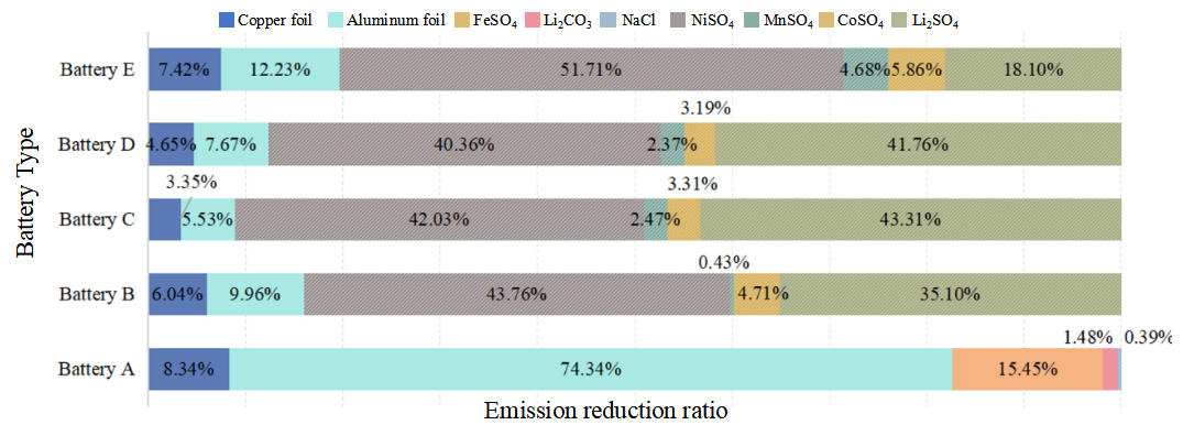
Figure 14. Emission reduction ratio for 1 kg of recycled battery materials.
Recycled materials from NMC batteries include copper foil, aluminum foil, nickel sulfate, manganese sulfate, lithium sulfate, and cobalt sulfate. Their emission reduction contributions vary by battery type. In general, aluminum achieves greater reductions than copper due to its higher content and greater carbon footprint per unit mass. Manganese sulfate shows the smallest emission reduction despite its higher mass in batteries C, D, and E (over three times more than cobalt). This indicates that manganese sulfate has a much smaller carbon footprint per unit of production than cobalt sulfate. Battery B shows the highest emission reductions for nickel sulfate (44.64%) and lithium sulfate (35.80%). Batteries C and D show similar trends, with lithium sulfate slightly outperforming nickel sulfate. In battery E, nickel sulfate contributes 51.72%, followed by lithium sulfate (18%). These figures suggest that the carbon emission savings from recycling nickel and lithium sulfates are nearly proportional to their recovered masses.
Even when the recycling processes are the same (i.e., the emissions from operations and reagent usage are similar), only battery C achieves a net carbon reduction. This is primarily due to its higher content of nickel, manganese, cobalt, and lithium, all elements with high production-related carbon footprints. The higher mass and higher emissions of these materials in battery C make its recycling more beneficial, with at least 1.44 times the recovery mass of other batteries.
Emission reduction from lightweight materials during recycling
Figure 15 compares the emission reduction performance of traditional materials versus CFRP used in the vehicle body, chassis, and balancing device during recycling. Regardless of material type, the emissions from the recycling process are lower than the emissions saved by material recovery, indicating overall carbon reduction potential. However, CFRP-based recycling processes and emissions from producing the recovered materials are much higher than those for steel or aluminum. This is mainly due to the intensive use of n-butanol and non-renewable electricity in CFRP recycling. While CFRP use in the vehicle body yields a relatively better reduction effect, its emission reduction accounts for only 10.7% of production emissions - much lower than 30.9% for traditional materials. For the chassis and balancing device, traditional materials offer greater carbon reduction potential. The emission reductions relative to production emissions are 60.9% and 75.7%, respectively, far exceeding CFRP’s 10.7%. This suggests that, at the current technological stage, traditional materials have higher carbon reduction value in the recycling phase, and CFRP should only be widely adopted once its production and recycling processes are optimized.
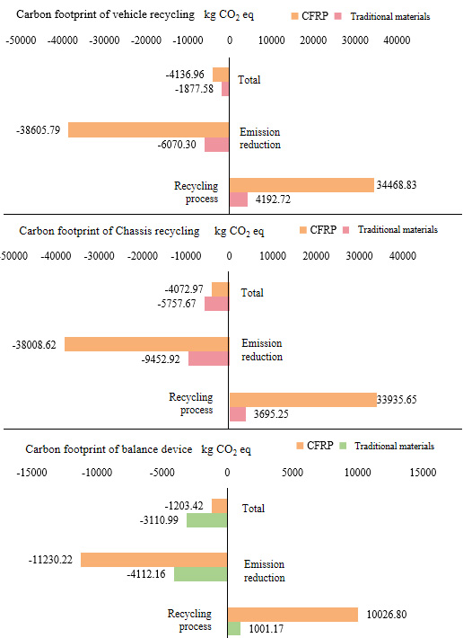
Figure 15. Emission reduction comparison using CFRP during the recycling stage. CFRP: Carbon fiber reinforced polymer.
Table 8 shows that despite using CFRP, emission reductions are still achieved during recycling. However, the carbon footprint of the recycling process is much higher than when traditional materials are used. The reduction in emissions from CFRP recycling is also relatively small. Moreover, the ratio of emissions saved through material recovery to emissions generated in the recycling process is lower than that of traditional materials. To promote efficient material recovery and reduce CO2 emissions across the automotive sector, further optimization of recycling processes is needed, specifically by reducing energy consumption, replacing high-carbon reagents, and improving material utilization efficiency.
Process emissions and emission reductions of electric buses using CFRP materials
| Electric bus recycling | Unit | A | B | C | D | E |
| Process emissions | kg CO2 eq | 91,838.49 | 95,157.21 | 9,2081.13 | 94,152.65 | 95,204.99 |
| Emissions from recovered material production | kg CO2 eq | 97,063.32 | 100,265.55 | 105,692.10 | 102,928.33 | 97,950.19 |
| Net reduction | kg CO2 eq | 5,224.83 | 5,108.34 | 13,610.97 | 8,775.68 | 2,745.19 |
| Reduction ratio | % | 5.69% | 5.37% | 14.78% | 9.32% | 2.88% |
CONCLUSION
Summary of findings
This study conducts a comprehensive life cycle carbon footprint assessment of electric buses equipped with different battery systems and structural materials. The main findings are as follows:
During the production stage, Bus C, which uses NMC batteries, exhibited the lowest carbon emissions at 55,814.89 kg CO2-eq, whereas Bus A, using LFP batteries, recorded the highest at 59,364.1 kg CO2-eq. Major contributors to emissions included battery production, bus body and chassis manufacturing, and electricity consumption. Although the use of CFRP materials significantly reduced vehicle weight, their production resulted in emissions 108.6% to 115.5% higher than those of conventional materials, offsetting their benefits at this stage.
In the usage stage, CFRP application led to an average vehicle weight reduction of 41.99%, which in turn reduced operational carbon emissions by 36.49%. Among the different electricity mix scenarios, Scenario 8 (2030) showed the highest emissions - 18% higher than the baseline. Conversely, Scenario 7 (2060) demonstrated the greatest emission reduction potential, reducing emissions by up to 86.5%. Scenario 6, characterized by a coal consumption rate of 200 g/kWh, reduced emissions by 48.6% compared to the current average of 435 g/kWh.
In the recycling stage, all bus systems achieved net carbon reductions relative to the emissions from producing virgin materials. Bus C achieved the largest reduction at 14,943.86 kg CO2-eq, equivalent to 26.77% of its production emissions, while Bus E achieved the smallest at 4,078.09 kg CO2-eq (7.15%). Among the five battery types, only Battery C demonstrated a net emission reduction through recycling. Key sources of emissions included electricity and liquid nitrogen in LFP battery recycling, as well as reagents such as tea polyphenols and NaOH in NMC battery recycling. Recovered materials like aluminum, nickel sulfate, and lithium sulfate significantly contributed to emission reductions. However, due to the high energy intensity of CFRP recycling, its overall carbon reduction effect remained limited compared to that of traditional materials.
In summary, this study highlights that substantial life cycle carbon reductions for electric buses can be achieved by optimizing material choices, advancing recycling technologies, accelerating the transition to clean electricity, and improving life cycle data transparency. These insights can inform policy interventions aimed at promoting low-carbon public transport in alignment with carbon neutrality goals.
Discussion and future research directions
This study offers a detailed life cycle assessment of electric buses under various battery technologies and power grid decarbonization scenarios, providing valuable insights into their relative carbon footprints. To achieve meaningful emission reductions, efforts should focus on enhancing electricity cleanliness, optimizing production processes, advancing CFRP and battery recycling technologies, and improving the efficiency of coal-fired power generation.
We acknowledge the uncertainties inherent in the parameters used. For instance, lower CFRP recycling efficiency could further diminish its already limited net emission reduction benefits, especially given its high production emissions. Similarly, rapid battery degradation would necessitate more frequent replacements, increasing upstream emissions. Conversely, advancements in battery longevity or material recovery technologies could significantly reduce life cycle emissions. These considerations underscore the importance of continued innovation in materials and recycling technologies. Future research should incorporate quantitative sensitivity analysis to better account for these uncertainties. Moreover, the use-phase analysis did not factor in variations such as passenger load, driving patterns, and climatic conditions, all of which can influence actual energy consumption. Although this study primarily focused on carbon emissions for clarity, future research should include other environmental impact categories, such as resource depletion and toxicity. Research into second-life battery applications, emerging recycling technologies, and cross-regional or dynamic scenario modeling would further strengthen the relevance and robustness of the findings.
Finally, the study’s outcomes offer clear policy and industrial implications. For policymakers, the results underscore the urgency of decarbonizing national power grids and developing standardized carbon footprint disclosure frameworks for electric vehicles across their life cycles. For manufacturers, the insights inform material selection strategies, particularly in weighing the trade-offs between lightweighting benefits and the production emissions of advanced materials such as CFRP. Additionally, the identified emission hotspots point to priority areas for technological innovation, such as boosting battery recycling efficiency and reducing the energy intensity of material recovery processes. Coordinated action at both the policy and industrial levels will be essential to advancing low-carbon public transportation systems.
DECLARATIONS
Authors’ contributions
Conceptualization, supervision, project administration, methodology development, modeling, and data analysis: Zhan, W.; Liu, Z.; Yu, Y.
Writing - original draft: Zhan, W.; Xue, B.; Yan, H.
Writing - manuscript review and revision: Zhan, W.; Li, X.; Wang, B.; Hu, Y.; Yu, J.; Liu, L.; Huang, K.
Availability of data and materials
The datasets generated and/or analyzed during the current study are available within this article and its Supplementary Materials. Further inquiries can be directed to the corresponding author.
Financial support and sponsorship
This research was supported by the National Natural Science Foundation of China (No. 52074037) and the National Key R&D Program of China (No. 2022YFB3305400).
Conflicts of interest
Huang, K. is an Editorial Board member of Carbon Footprints. Huang, K. was not involved in any part of the editorial process, including reviewer selection, manuscript handling, or decision making. The other authors declared that there are no conflicts of interest.
Ethical approval and consent to participate
Not applicable.
Consent for publication
Not applicable.
Copyright
© The Author(s) 2025.
Supplementary Materials
REFERENCES
1. Zhu, M.; Liu, Z.; Li, J.; Zhu, S. X. Electric vehicle battery capacity allocation and recycling with downstream competition. Eur. J. Oper. Res. 2020, 283, 365-79.
2. Yu, X.; Ji, Z.; Ji, L.; et al. Analysis on carbon emission reduction potential of electric vehicles in China under goal of carbon neutrality and carbon peaking. Smart. Power. 2024, 52, 25-31+39. Available from: http://zhdlqk.sn.sgcc.com.cn:19001/#/digest?ArticleID=5864 [Last accessed on 23 July 2025].
3. Shi, Y.; Zhang, H.; Yu, Z. Energy saving and emission reduction benefits analysis and environmental impact assessment of electric vehicles throughout their entire lifecycle. Resour Ind 2021;23:100-9.
4. European Commission. A European strategy for low-emission mobility. Brussels, Belgium: 2016. Available from: https://ec.europa.eu/commission/presscorner/detail/nl/memo_16_2497 [Last accessed on 23 July 2025].
5. Ministry of Industry and Information Technology of the People’s Republic of China industrial green development plan (2016-2020). Energy saving in non-ferrous metallurgy 2016:1-7. Available from: https://www.miit.gov.cn/jgsj/jns/wjfb/art/2020/art_d66bb56744d9433d827bdb571de9a250.html [Last accessed on 25 July 2025].
6. Huang, W.; Zhang, X. Life cycle analysis of vehicle biogas for city bus. J. Transp. Syst. Eng. Inf. Technol. 2016, 16, 44-8. Available from: http://www.tseit.org.cn/CN/Y2016/V16/I2/44 [Last accessed on 25 July 2025].
7. Arribas-ibar, M.; Nylund, P.; Brem, A. The risk of dissolution of sustainable innovation ecosystems in times of crisis: the electric vehicle during the COVID-19 pandemic. Sustainability 2021, 13, 1319.
8. Deliali, A.; Chhan, D.; Oliver, J.; Sayess, R.; Godri, Pollitt. K. J.; Christofa, E. Transitioning to zero-emission bus fleets: state of practice of implementations in the United States. Transp. Rev. 2021, 41, 164-91.
9. Waisman, H.; De, Coninck. H.; Rogelj, J. Key technological enablers for ambitious climate goals: insights from the IPCC special report on global warming of 1.5 °C. Environ. Res. Lett. 2019, 14, 111001.
10. Cusenza, M. A.; Bobba, S.; Ardente, F.; Cellura, M.; Di, Persio. F. Energy and environmental assessment of a traction lithium-ion battery pack for plug-in hybrid electric vehicles. J. Clean. Prod. 2019, 215, 634-49.
11. Lopez, S.; Akizu-Gardoki, O.; Lizundia, E. Comparative life cycle assessment of high performance lithium-sulfur battery cathodes. J. Clean. Prod. 2021, 282, 124528.
12. Bibra, E. M.; Connelly, E.; Dhir, S.; et al. Global EV outlook 2022: securing supplies for an electric future. 2022. Available from: https://trid.trb.org/View/2005689 [Last accessed on 23 July 2025].
13. Zeng, X.; Li, M.; Abd, El-hady. D.; et al. Commercialization of lithium battery technologies for electric vehicles. Adv. Energy. Mater. 2019, 9, 1900161.
14. Filote, C.; Felseghi, R.; Raboaca, M. S.; Aşchilean, I. Environmental impact assessment of green energy systems for power supply of electric vehicle charging station. Int. J. Energy. Res. 2020, 44, 10471-94.
15. Thorne, R.; Aguilar, Lopez. F.; Figenbaum, E.; Fridstrøm, L.; Müller, D. B. Estimating stocks and flows of electric passenger vehicle batteries in the Norwegian fleet from 2011 to 2030. J. Ind. Ecol. 2021, 25, 1529-42.
16. Knobloch, F.; Hanssen, S.; Lam, A.; et al. Net emission reductions from electric cars and heat pumps in 59 world regions over time. Nat. Sustain. 2020, 3, 437-47.
17. Feng, T.; Guo, W.; Li, Q.; Meng, Z.; Liang, W. Life cycle assessment of lithium nickel cobalt manganese oxide batteries and lithium iron phosphate batteries for electric vehicles in China. J. Energy. Storage. 2022, 52, 104767.
18. Degen, F.; Mitterfellner, M.; Kampker, A. Comparative life cycle assessment of lithium-ion, sodium-ion, and solid-state battery cells for electric vehicles. J. Ind. Ecol. 2025, 29, 113-28.
19. Li, Y.; Hua, Z.; Feng, T.; et al. Environmental influence evaluation of the fuel full life cycle of city buses with different energy sources based on GREET software. Bus. Technol. Res. 2022, 44, 52-5. Available from: https://d.wanfangdata.com.cn/periodical/kcjsyyj202201016 [Last accessed on 23 July 2025].
20. Pan, Y. Analysis and estimation of emission characteristics of new energy buses based on multi-source data. Southeast University, 2020.
21. Golkaram, M.; Ligthart, T.; Yildiran, A.; et al. Future options and their impact on the life cycle assessment and life cycle costing of segment c/d passenger vehicles. Rosearch Square 2024.
22. Zhao, C.; Kobayashi, L. Z.; Alquaity, A. B. S.; et al. Solutions for decarbonising urban bus transport: a life cycle case study in Saudi Arabia. Commun. Eng. 2024, 3, 238.
23. Ankathi, S.; Gan, Y.; Lu, Z.; et al. Well-to-wheels analysis of greenhouse gas emissions for passenger vehicles in Middle East and North Africa. J. Ind. Ecol. 2024, 28, 800-12.
24. Zhang, S.; Wu, Y.; Liu, H.; et al. Real-world fuel consumption and CO2 emissions of urban public buses in Beijing. Appl. Energy. 2014, 113, 1645-55.
25. Takahashi, R.; Negishi, K.; Noda, H.; Mizutani, M. Estimating the dominant life phase concerning the effects of battery degradation on CO2 emissions by repetitive cycle applications: case study of an industrial battery system installed in an electric bus. Energies 2023, 16, 1508.
26. Tintelecan, A.; Dobra, A. C.; Marțiș, C. Literature review - electric vehicles life cycle assessment. 2020. ELEKTRO. , IEEE,2020; pp. 1-6.
27. Zhang, X.; Li, L.; Fan, E.; et al. Toward sustainable and systematic recycling of spent rechargeable batteries. Chem. Soc. Rev. 2018, 47, 7239-302.
28. Walvekar, H.; Beltran, H.; Sripad, S.; Pecht, M. Implications of the electric vehicle manufacturers’ decision to mass adopt lithium-iron phosphate batteries. IEEE. Access. 2022, 10, 63834-43.
29. Chen, Z.; Deng, Y.; Li, H.; Liu, W. An efficient regrouping method of retired lithium-ion iron phosphate batteries based on incremental capacity curve feature extraction for echelon utilization. J. Energy. Storage. 2022, 56, 105917.
30. Penisa, X. N.; Castro, M. T.; Pascasio, J. D. A.; Esparcia, E. A.; Schmidt, O.; Ocon, J. D. Projecting the price of lithium-ion NMC battery packs using a multifactor learning curve model. Energies 2020, 13, 5276.
31. Tolomeo, R.; De, Feo. G.; Adami, R.; Sesti, Osséo. L. Application of life cycle assessment to lithium ion batteries in the automotive sector. Sustainability 2020, 12, 4628.
32. Wu, H.; Gong, Y.; Yu, Y.; Huang, K.; Wang, L. Superior “green” electrode materials for secondary batteries: through the footprint family indicators to analyze their environmental friendliness. Environ. Sci. Pollut. Res. 2019, 26, 36538-57.
33. Accardo, A.; Dotelli, G.; Musa, M. L.; Spessa, E. Life cycle assessment of an NMC Battery for application to electric light-duty commercial vehicles and comparison with a sodium-nickel-chloride battery. Appl. Sci. 2021, 11, 1160.
34. Petrauskienė, K.; Skvarnavičiūtė, M.; Dvarionienė, J. Comparative environmental life cycle assessment of electric and conventional vehicles in Lithuania. J. Clean. Prod. 2020, 246, 119042.
35. Liu, J. Research on life cycle assessment of hydrogen fuel cell vehicles. Xi’an: Chang’an University, 2020.
36. Liu, K.; Xu, J. Life cycle assessment of driving motor on electric vehicle. J. Environ. Sci. 2016, 36, 3456-63.
37. Evangelisti, S.; Tagliaferri, C.; Brett, D. J.; Lettieri, P. Life cycle assessment of a polymer electrolyte membrane fuel cell system for passenger vehicles. J. Clean. Prod. 2017, 142, 4339-55.
38. Liu, W.; Huang, H.; Liu, Y.; Li, L.; Cheng, H.; Liu, Z. Life cycle assessment and energy intensity of CFRP recycling using supercritical N-butanol. J. Mater. Cycles. Waste. Manag. 2021, 23, 1303-19.
39. Zackrisson, M. Life cycle assessment of long life lithium electrode for electric vehicle batteries:cells for Leaf, Tesla and Volvo bus. Swerea IVF Uppdragsrapporter, Swerea IVF AB, 2017: 56. Available from: https://ri.diva-portal.org/smash/record.jsf?pid=diva2%3A1131667&dswid=-5226 [Last accessed on 25 July 2025].
40. Que, T.; Xie, Y. Carbon capture and storage technology helps achieve carbon neutrality goals. China Soc. Sci. J. 2022, 006. Available from: https://epaper.csstoday.net/epaper/read.do?m=i&iid=6413&eid=45124&sid=208935&idate=12_2022-10-25_A06 [Last accessed on 23 July 2025].
41. Liu, S.; Jiang, Y.; Yu, S.; Tan, W.; Zhang, T.; Lin, Z. Electric power supply structure transformation model of China for peaking carbon dioxide emissions and achieving carbon neutrality. Energy. Rep. 2022, 8, 541-8.
43. Ruan, R.; Zhong, S.; Wang, D. Life cycle assessment of biological copper extraction and pyrometallurgical copper refining processes. Multipurp. Util. Miner. Resour. 2010, 6, 33-7. Available from: https://kns.cnki.net/kcms2/article/abstract?v=5ykJdPmCibK_Yr-c9kdTPVX9-1COKWA5Cm9yuoRC0FQBOCMAKVBp_8YuJaYFFJffp4bS-arrMRJkN8ejbK7s-gbEpcYe-cS6Zfq9Jsz9IFYM1T_yP3mgNlYAzJLdDiVza4mnSPKI-YANCQpd3bwS5ryttiMfhPwK2AAmd_Zog8NSYj-skM6cQw==&uniplatform=NZKPT&language=CHS [Last accessed on 23 July 2025].
44. Zhang, B. Energy consumption in casting production. Modern. Cast. Iron. 2006, 26, 58-60. Available from: https://kns.cnki.net/kcms2/article/abstract?v=d24vdHNzaZhyahlYi_qnS92DeTtyOEiAKeeUuaDaY2Dk3K1JmELr09X0rxoWx3Pql68YnJsqm4KmaijtwquK87XzZHg1XhSoJ5rAM1PwfT4V1EwPVc95o8qQDwx8Ryy2nRQ17QWhalQMokneT71Il2EBHzx4X8vE9v6NUBCFkq0=&uniplatform=NZKPT [Last accessed on 23 July 2025].
45. Chen, Y.; Hu, X.; Liu, J. Life cycle assessment of fuel cell vehicles considering the detailed vehicle components: comparison and scenario analysis in China based on different hydrogen production schemes. Energies 2019, 12, 3031.
46. Natarajan, S.; Aravindan, V. An urgent call to spent LIB recycling: whys and wherefores for graphite recovery. Adv. Energy. Mater. 2020, 10, 2002238.
47. Wang, Z. Potential and life cycle assessment of recycling and utilization of power batteries for new energy vehicles. Beijing: Tsinghua University, 2018.
48. Liu, K.; Wang, M.; Zhang, Q.; et al. A perspective on the recovery mechanisms of spent lithium iron phosphate cathode materials in different oxidation environments. J. Hazard. Mater. 2023, 445, 130502.
49. James, S. L.; Adams, C. J.; Bolm, C.; et al. Mechanochemistry: opportunities for new and cleaner synthesis. Chem. Soc. Rev. 2012, 41, 413-47.
51. Zhang, Y.; Ning, P.; Yang, X.; et al. New progress in research on recycling technology of waste ternary lithium-ion batteries. Chem. Prog. 2020, 39, 2828-40.
52. Xie, Y.; Yu, H.; Ou, Y.; Li, C. Environmental impact assessment of recycling waste traction battery. Inorg. Salt. Ind. 2015, 47, 43-46+61. Available from: https://www.wjygy.com.cn/CN/Y2015/V47/I4/43?utm_source=chatgpt.com [Last accessed on 23 July 2025].
53. Li, K. Research on the recovery technology of valuable metals in waste ternary lithium battery cathode materials. Beijing University of Chemical Technology, 2022.
54. Jiang, S.; Hua, H.; Zhang, L.; Liu, X.; Wu, H.; Yuan, Z. Environmental impacts of hydrometallurgical recycling and reusing for manufacturing of lithium-ion traction batteries in China. Sci. Total. Environ. 2022, 811, 152224.
55. Ghosh, T.; Kim, H. C.; De, Kleine. R.; Wallington, T. J.; Bakshi, B. R. Life cycle energy and greenhouse gas emissions implications of using carbon fiber reinforced polymers in automotive components: Front subframe case study. Sustain. Mater. Technol. 2021, 28, e00263.
56. Koffler, C. Life cycle assessment of automotive lightweighting through polymers under US boundary conditions. Int. J. Life. Cycle. Assess. 2014, 19, 538-45.
57. Kumanan, A.; Varadarajan, S.; Narayanan, K. Lightweighting in electric vehicles: review of the design strategies based on patents and publications. In: Chakrabarti A, Poovaiah R, Bokil P, Kant V, editors. Design for Tomorrow-Volume 3. Singapore: Springer; 2021. pp. 263-72.
58. Ebrahimi, S.; Koh, L. Manufacturing sustainability: Institutional theory and life cycle thinking. J. Clean. Prod. 2021, 298, 126787.
Cite This Article
How to Cite
Download Citation
Export Citation File:
Type of Import
Tips on Downloading Citation
Citation Manager File Format
Type of Import
Direct Import: When the Direct Import option is selected (the default state), a dialogue box will give you the option to Save or Open the downloaded citation data. Choosing Open will either launch your citation manager or give you a choice of applications with which to use the metadata. The Save option saves the file locally for later use.
Indirect Import: When the Indirect Import option is selected, the metadata is displayed and may be copied and pasted as needed.
About This Article
Copyright

Data & Comments
Data
0


Comments
Comments must be written in English. Spam, offensive content, impersonation, and private information will not be permitted. If any comment is reported and identified as inappropriate content by OAE staff, the comment will be removed without notice. If you have any queries or need any help, please contact us at [email protected].