
LCA-based environmental sustainability assessment of hybrid additive manufacturing of a turbine blade

 ,
, Abstract
In this paper, a cradle-to-gate life cycle assessment (LCA) method is used to compare the overall energy consumption and environmental impact of hybrid additive manufacturing (HAM) and the traditional CNC milling process with a case study of turbine blade manufacturing. Six environmental impacts are assessed in this study: acidification potential (AP), eutrophication potential (EP), global warming potential (GWP), photochemical ozone creation potential (POCP), ozone depletion potential (ODP), and abiotic depletion potential (ADP). The results suggest that HAM can not only reduce energy consumption and material waste but also reduce the environmental impact by 53% from a life cycle perspective. Specifically, the results of GWP, AP, EP, ODP, POCP and ADP of the HAM are only 32.2%, 34.6 %, 44.7%, 27.2%, 25.6%, and 24.7 % of that in traditional CNC machining.
Keywords
INTRODUCTION
Additive manufacturing (AM) is leading a fundamental shift in the way we design and manufacture products[1]. AM has become the mainstream in the manufacturing landscape due to its numerous benefits, including design freedom, material saving, and the reduction of production cost and manufacturing carbon footprint[2]. However, the adoption of AM in industries is still at a very early stage due to various technical challenges, such as lack of manufacturing tolerance, poor surface finish, a requirement for post-processing, etc.[3]. Recently, an emerging hybrid additive manufacturing (HAM) technology has enabled the industry to reap the full potential of AM. HAM is defined as the use of AM with one or more secondary processes that are fully coupled and synergistically affect part functionality and process performance[4]. Secondary processes include subtractive and deformative manufacturing technologies, such as machining, abrasive blasting, peening, chemical etching, and sintering, etc. Implementation of HAM technology will enhance AM’s capabilities in creating high-geometrical-complexity and high-accuracy 3D structures with a smooth surface finish[5].
DED is one of the laser-based AM processes in which three-dimensional parts can be directly fabricated from raw materials with a layer additive method[6]. Due to the unique capability to fabricate fully dense metal components and outstanding as-fabricated mechanical properties, DED is developing into a promising technology for structural coating[7], free-form fabrication[8], and component repair[9]. Combining additive DED and subtractive CNC machining in a single machine has become the main form in the HAM market, and it enables fabricating a near-net-shape part in a single setup without a need for
HAM is of great interest to the precision industry because it will not only reduce manufacturing costs but increase the economic competitiveness of technological companies. Recently, HAM was successfully applied in repairing a damaged mold, and it was proved that HAM shows a reduction of the environmental impacts and life cycle costs by avoiding resource consumption in the production of a new mold[13]. However, like any other new technology, HAM faces a set of challenges, including process planning, quality control and assurance, and sustainability[4]. Currently, AM community is not only focusing on quality assurance but also on energy and environmental impact due to natural resource depletion and environmental degradation[14]. As a result, the AM industry is now having three primary targets: sustainability, quality assurance, and
Despite the great potential to reduce cost and material waste, the sustainability performance of HAM over traditional manufacturing is still not clear. In this study, a comparative sustainability assessment was performed for DED-based HAM and traditional CNC Milling for a turbine blade. The goal is to identify the key factors triggering the environmental impacts of these two manufacturing processes and to reduce the environmental impacts to make the processes more sustainable. Cradle-to-gate life cycle assessment (LCA) was applied to build the life cycle models and calculate the energy consumption and environmental impacts of these two manufacturing processes. The results of this study can provide guidance and convincing information when judging the environmental benefits of HAM over CNC Milling. It can also provide a comprehensive view of HAM, thus helping decision-makers select a more sustainable solution. The rest of the paper is organized as follows. In Section 2, the related work on the sustainability assessment of the metal AM processes is discussed. In Section 3, we describe the LCA procedures. Section 4 describes the experimental setup and data collection. In Section 5, the sustainability performance of the two manufacturing processes is evaluated. The effects of life cycle activities on sustainability performance are also evaluated. Section 6 summarizes the conclusions and future work.
RELATED WORK
Many studies have been performed on the sustainability assessment of various metal AM processes. From a life cycle perspective, Simon Ford et al. investigated the sustainable benefits of AM over traditional manufacturing from four aspects, including process redesign, material input, make-to-order components, and product manufacturing[15]. Liu et al. compared the energy demand of the HAM process and CNC machining process for bearing bracket manufacturing. They found that the manufacturing phase in the HAM process consumed most of the energy, while the material production in the CNC machining process accounts for the largest proportion of energy consumption[16]. From a generalized perspective, AM is considered more sustainable than traditional manufacturing because it has higher efficient energy and less material usage[3]. The environmental performance of metal AM varies case by case. It has been proved that the environmental performance of metal AM is directly related to the part size and the volume of material removal in post-processing[17]. LCA and specific energy consumption (SEC) are commonly used to determine the sustainability assessment of metal AM, as summarized in Table 1.
Summary of sustainability assessment between metal AM and traditional manufacturing
| Metal AM | Traditional manufacturing | Method used | Major findings | Ref. |
| PBF | Casting and machining | LCA | The weight reduction potential of AM helps improve the environmental performance | [16] |
| PBF | Milling | LCA | PBF is more environment-friendly for parts with complex shape and geometry | [17] |
| PBF | N/A | LCA | A proper design for AM is important to improve the overall energy and emission-saving potential | [18] |
| PBF | CNC machining | LCA | PBF has a significant environmental advantage compared to the traditional technology | [19] |
| PBF | Casting and machining | LCA | The environmental impact of PBF without optimization was 37.42% lower than that of CM | |
| DED | Forging and machining | LCA | For cylinder head repairing, DED cuts more than 60% of environmental impact over the entire life cycle | [21] |
| DED | CNC machining | LCA | DED has 70% less environmental impact than conventional manufacturing | [22] |
| DED | CNC milling | SEC | DED has less manufacturing time (4%) and energy consumption (80%) compared with CNC | [23] |
Due to the layer-upon-layer fabrication, AM is more suitable for small-batch production. With the increasing production volume and part complexity level, the production cost and energy consumption per unit part remain consistent. For traditional manufacturing, such as casting, forging, and CNC milling, where tooling and mold are needed, the cost and energy consumption increase with part complexity level, but reduce with the increasing production volume. Both quantitative and qualitative methods have been applied in the sustainability assessment of the DED AM process, including LCA, environmental impact/risk assessment, multi-criteria decision analysis, risk management, etc. HAM is a complex manufacturing system combining additive DED and subtractive CNC machining. The material, energy, and waste flows are apparently different from those in traditional manufacturing, which brings challenges to its environmental sustainability assessment. The major challenges include: (1) drawing a complete boundary of the assessment; (2) data collection and evaluation; and (3) scientific assessment of environmental emissions. Also, parts with different materials, sizes, designs, and complexity will affect the overall sustainability performance.
MATERIALS AND METHODOLOGY
Material and specimen design
In this study, a general turbine blade used in the air compressor is selected. The design before and after HAM is shown in Figure 1. To ensure a sufficient height at the corner area, some extra margin is added to the design, which later would be removed with post-machining. Stainless steel 316 L (SS 316 L) is used to fabricate the turbine blade because of its relatively high strength, good corrosion resistance, and large internal friction or damping capacities. As received SS 316 L powder (45-106 μm) from Carpenter is used in HAM, and bulk SS 316 L is used in CNC machining.

Figure 1. Designed turbine blade (mass: 40 g, height: 15 mm) (A) Before HAM (B) after HAM.
Life cycle assessment
LCA is a useful tool to evaluate and assess the environmental aspects of a product or a process[24]. LCA provides a comprehensive view of the environmental aspects by estimating the cumulative environmental impacts resulting from the entire product life cycle[25]. As a systematic approach, an LCA consists of four components: (a) goal and scope definition; (b) life cycle inventory (LCI); (c) life cycle impact assessment (LCIA); and (d) life cycle interpretation[26]. The following sections describe these steps in detail.
Goal and scope definition
The goal of this LCA is to quantify and compare the environmental impacts caused by different processes associated with the DED-based HAM of a turbine blade with its counterpart manufactured by traditional CNC machining. In LCA, the functional unit needs to be defined to compare the two systems with normalized inputs and outputs. In this study, the functional unit is a single turbine blade, which can extract energy from the high-temperature, high-pressure gas produced by the combustor.
System boundary must also be defined in LCA, and environmental impacts outside the boundary are ignored. To provide a comprehensive and highly accurate evaluation result, the system boundary must include all life cycle stages, significant energy uses, material flows, and environmental emissions in both the HAM and the CNC machining system. As shown in Figures 2 and 3, both two systems start with the same resources (iron ore), and both provide the same turbine blade part. However, the paths from resources to the final parts are quite different. The HAM system includes the following steps: raw material production from iron ore, transportation of raw material to the powder manufacturing and rolling site, steel substrate manufacturing via rolling, powder production via gas atomization, transportation of powder and steel substrate to the DED lab, turbine blade fabrication via DED, heat treatment, post-processing via CNC finishing. The CNC machining system starts with raw material production, going through the transportation of raw material to the casting/forging site, steel production, transportation of processed steel to the CNC lab, turbine blade manufacturing via CNC machining, heat treatment, and surface finishing. The distribution, usage, and disposal of the two manufacturing processes are considered equivalent and excluded outside the boundary.

Figure 2. Detailed process flow diagram for HAM.

Figure 3. Detailed process flow diagram for CNC Machining.
Life cycle inventory
Life cycle inventory (LCI) is to quantify energy and raw material requirements, atmospheric emissions, waterborne emissions, solid waste, and other releases for the entire life cycle of a product, process, or activity. A data collection plan is needed to ensure that the quality and accuracy of data meet the expectations of the decision-makers. In this study, material consumption, transportation, energy consumption, and environmental emissions data will be collected from three major sources: the USLCI database in GaBi software, literature and prior research, and data collected by the performer. Gabi professional (version 10.6, Sphera Solutions GmbH, Leinfelden, Germany) is used for life cycle modeling. GaBi offers access to comprehensive and user-friendly functionality to analyze product life cycles or process technologies to deal with LCA[27]. The USLCI database in GaBi provides individual gate-to-gate, cradle-to-gate, and cradle-to-grave accounting of the energy and material flows into and out of the environment that are associated with producing a material, component, or assembly in the U.S[28]. The data collection plan for the two manufacturing processes is summarized in Table 2.
Summary of data collection plan of two manufacturing processes
| Process name | Life cycle flows | Data source | Data type |
| HAM | Raw material production | USLCI, GaBi | Modeled |
| Gas atomization | Literature[29] | Calculated | |
| Transportation | USLCI, GaBi | Modeled | |
| Part fabrication via DED | Lab test | Measured | |
| Heat treatment | GaBi /Lab Test | Modeled/Measured | |
| Part finishing via CNC | Lab test | Measured | |
| Tool manufacturing | Literature[30-31] | Calculated | |
| Energy production | USLCI, GaBi | Modeled | |
| Environmental emissions | USLCI, GaBi | Modeled | |
| CNC | Raw material production | USLCI, GaBi | Modeled |
| Casting/Forging | GaBi | Calculated/ Modeled | |
| Transportation | USLCI, GaBi | Modeled | |
| CNC machining | Lab test | Measured | |
| Tool manufacturing | Literature[30-31] | Calculated | |
| Heat treatment | GaBi /Lab Test | Modeled/Measured | |
| Surface finishing (Grinding) | Lab test | Measured | |
| Energy production | USLCI, GaBi | Modeled | |
| Environmental emissions | USLCI, GaBi | Modeled |
(1) Material production
The materials directly consumed in the HAM process include steel billet, metal powder, and argon. Cradle-to-gate unit processes in USLCI: “Steel, billets, at plant” and “Argon, air, at plant” is used as the elementary flow for steel and argon production separately. The powders are manufactured via the gas atomization process, where the powder is formed by blowing high-pressure gas against high-temperature molten metal so that it scatters and hardens into particles as it cools while falling[29]. The materials directly consumed in the CNC machining include steel billet and coolant. Cradle-to-gate unit processes in USLCI: “Steel, billets, at plant” and “Coolant at refinery” is used as the elementary flow for steel and coolant production separately.
(2) Transportation
The steel plate was ordered from Mcmaster-Carr and it was shipped from McMaster, OH to the lab with a total distance of 170 miles. The powder was ordered through Carpenter Technology Corporation, PA. An average distance of 250 miles was used as the travel distance of the steel billet from the steel production company to Carpenter; the powder after gas atomization traveled 65 miles from Carpenter to the lab. Unit processes in USLCI: “Transport, single-unit truck, diesel-powered, Northeast” was used as the elementary flow in material transportation.
(3) Part fabrication
The blades were manufactured with a customized powder-based HAM system (AMBITTM core DED, Hybrid Manufacturing Technology, TX, USA). The system consists of an inert gas supply, a system chamber including the X-Y axes motion table, the deposition head and the lens system, powder hoppers, AMBIT core, operator control, a chiller, and a fume extractor, as shown in Figure 4. SS 316 L powders are delivered to the deposition head with delivery gas (argon), and the powder feeding rate is controlled with the rotational disk in the hoppers. Inert gas is supplied to the system’s chamber to avoid oxidation during the print. The path of the deposition head is generated by Autodesk Fusion 360 and controlled by the AMBITTM core. Onset UX-120-017, HOBO 4-Channel pulse data loggers are used to collect energy consumption during the part manufacturing processes. The ampere value was recorded for every

Figure 4. AMBITTM core hybrid manufacturing system.
DED module in HAM machine is used to fabricate the part, and then the as-deposited part is machined with facing and contouring with CNC module in HAM after cooling. It took 24 min for the part fabrication and 30 min to do the post-processing. For traditional manufacturing, it used two paths to machine the block to the final part and took 60 min in total. Cutting tools and coolant are needed in CNC finishing; however, their environmental impact is often ignored due to the difficulties in data collection[30]. In this study, carbide tools are used for CNC machining. Considering the energy embodied in the tooling material and the energy needed for tool production, the total energy consumption of a cutting tool with a weight of 9.5 g is
Process parameters used for the part manufacturing via DED and CNC
| Process parameters | Value | |
| DED | Laser power (W) | 900 |
| Layer thickness (mm) | 1.5 | |
| Infill density (%) | 80 | |
| Infill orientation (°) | 0, 45, 135, 45, 0 | |
| Scanning speed (mm/s) | 10 | |
| Powder flow (g/min) | 5 | |
| Carrier gas flow rate (L/min) | 5 | |
| Shield gas flow rate (L/min) | 12 | |
| Substrate temperature (oC) | 20 | |
| The volume of stock (mm3) | 1775 | |
| CNC | Spindle speed (rpm) | 1527 |
| Spindle power (kW) | 0.6 | |
| Chip load (mmp) | 0.051 | |
| Feed rate (mm/min) | 155.20 | |
| Coolant mass flow rate (Kg/min) | 0.2 | |
Figure 5 illustrated the time series data of electricity consumption during part manufacturing. For DED, the current flow keeps dropping and then going up again according to the tool path, as the tool path follows the same for different layers. For CNC, the current flow remains almost consistent during the finishing process. To calculate the energy consumption (E, kWh), the below formula was used:


Figure 5. Energy consumption trend in DED and CNC.
Where P is power (watt), t is the processing time (min), V is voltage (240 V), I is the current (ampere), pfis the power factor by the logger (pf = 0.9). With the time series data collected for the logger, energy consumption is calculated for the part manufacturing. The material and energy consumption during HAM and CNC are shown in Figure 6. The Buy-to-Fly ratio is the ratio of the mass of the starting billet of material to the mass of the final, finished part. The Buy-to-Fly ratio of HAM (1.34:1) is much smaller than that of CNC machining (5.53:1). “Electricity, lignite coal, at power plant” in USLCI is used as the unit process for energy consumption.

Figure 6. Energy and material consumption for the HAM/CNC process.
With the collected LCI data, the life cycle of HAM and CNC for the blades is modeled and analyzed in GaBi, as shown in Figures 7 and 8.

Figure 7. Life cycle model of the HAM process in GaBi professional.

Figure 8. Life cycle model of the CNC process in GaBi professional.
Life cycle impact assessment
Life cycle impact assessment (LCIA) is performed to translate the inputs and outputs into environmental impacts. According to ISO 14044 standard, the LCIA phase consists of four consecutive steps: (1) Classification, to sort all substances into different classes based on their effect on the environment; (2) Characterization, to quantify the environmental impact a product or service in each impact category; (3) Normalization, to compare the quantified impact to a certain reference value; and (4) Weighting, to assign impact categories an importance value, and the resulting figures are used to generate a single score.
(1) Classification
CML (Institute of Environmental Sciences) 2001, a “midpoint” approach, was used as the classification method used in this analysis[32]. Five environmental impact categories are evaluated, including acidification potential (AP), eutrophication potential (EP), global warming potential (GWP), photochemical ozone creation potential (POCP), and ozone depletion potential (ODP). Additionally, a single-issue energy category known as abiotic depletion potential (ADP) is also considered.
(2)Characterization & Normalization
In this step, all substances are multiplied by a characterization factor (CF) that reflects their relative contribution to the environmental impact. Ranking the impact categories after characterization, e.g., comparing the impact of GWP and AP, is difficult. Therefore, ISO 14044[26] suggests using normalization to compare different impact category indicators. In normalization, the magnitude of the results of impact category indicators is calculated based on certain reference information. The characterized results of each impact category are divided by a selected reference value, which brings all the results on the same scale, as expressed in Equation (2).

where Ni is the normalized results, i is the impact category, Si is the characterized impact of the impact category i of the system under study, and Ri is the characterized impact of the impact category i of the reference system. In this study, the total inputs, and outputs for a geographical given area over a given reference year on a per capita basis are used as the reference system. The results of LCI were characterized based on CML 2001 and normalized against per capita global impact for the year 2000[33]. The normalized result based on LCI for HAM and CNC is shown in Table 4.
LCIA results for HAM and CNC
| Environmental impact | Characterization result | Normalization factor | Normalized environmental impact | Weighting factor | Environmental load unit | |||
| HAM | CNC | HAM | CNC | HAM | CNC | |||
| GWP (Kg CO2 Equiv.) | 9.31E+00 | 1.96E+01 | 4.15E+13 | 2.24E-13 | 4.72E-13 | 1.1 | 1.06E-12 | 2.25E-12 |
| AP (Kg SO2 Equiv.) | 1.09E-01 | 2.06E-01 | 2.39E+11 | 4.56E-13 | 8.62E-13 | 1.3 | ||
| EP (Kg NO3 Equiv.) | 3.33E-03 | 4.12E-03 | 1.58E+11 | 2.11E-14 | 2.61E-14 | 1 | ||
| ODP (Kg CFC II Equiv.) | 3.50E-09 | 9.35E-09 | 5.01E+06 | 6.99E-16 | 1.87E-15 | 63 | ||
| POCP (Kg C2H4 Equiv.) | 4.91E-03 | 1.43E-02 | 4.01E+10 | 1.22E-13 | 3.57E-13 | 1.3 | ||
| ADP (Kg Sb Equiv.) | 1.66E+02 | 5.05E+02 | 1.56E+11 | 1.06E-09 | 3.24E-09 | - | - | - |
(3) Weighting
Weighting helps to present LCA results as a single score. It allows you to easily compare the environmental impact of different products or scenarios. The weighting result can be calculated with Equation (3).

Where W is the weighted result, WFcis the weighting factor for this impact category, and Ic symbolizes the impact score or normalized impact score for impact category c. In this study, the distance-to-target (DTT) method derived from EDIP97 is used[34]. Table 4 shows the weighting factors and results based on the DTT method. After adding the value for each impact category, the Environmental Lead Unit for each manufacturing strategy can be calculated.
RESULT AND DISCUSSION
Life cycle environmental impact analysis
LCIA results in Table 4 suggest that the environmental load unit of HAM is less than that of CNC for the designed turbine blade manufacturing. Assuming that part quality of the two manufacturing processes is equivalent, HAM can help to reduce the environmental impact by 53% from a life cycle perspective. Figure 9 shows the normalized environmental impact of HAM and CNC, indicating that ADP and AP are the two most significant impact categories for both two manufacturing strategies, followed by GWP and POCP. The quantities of EP and ODP are relatively small.

Figure 9. Normalized environmental impacts of HAM and CNC.
Figure 10 shows the percentages of each environmental impact to the total. The results of GWP, AP, EP, ODP, POCP, and ADP of the HAM are only 32.2%, 34.6%, 44.7%, 27.2%, 25.6%, and 24.7% of that in traditional CNC machining. The reason is that more energy is consumed in CNC machining processes. On the other hand, the raw material consumption in CNC is more than that of HAM due to a higher buy-to-fly ratio (5.53:1 vs. 1.34:1), meaning that more materials needed to be removed in the CNC process.

Figure 10. Percentages of each environmental impact to the total.
Energy consumption analysis
Energy is required and consumed for each life cycle process in both HAM and CNC. From the life cycle perspective, the total energy consumption of HAM (EHAM, MJ) and CNC (ECNC, MJ) can be calculated with Equations (4) and (5).
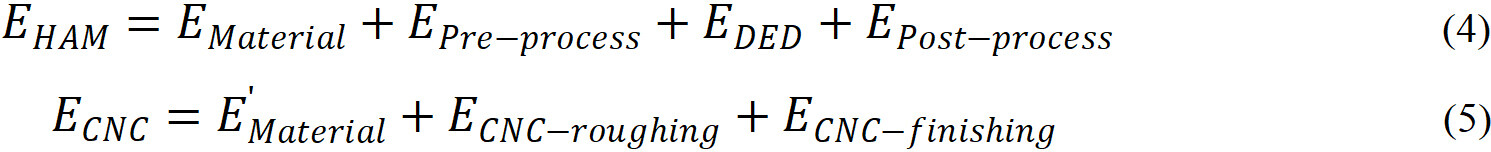
Where Ematerial includes energy consumption of powder and substrate, Epre-process includes the energy consumption during build preparation, EPost-processingis the energy consumption in surface finishing. E'Material is the energy consumption of the bulk material, ECNC-roughingand ECNC-finishingrepresent the energy consumption in roughing and finishing processes of CNC machining. The result of the ADP fossil in Figure 11 indicates that a large amount of coal, crude oil, and natural gas is used in electricity production. For HAM, the energy is mainly produced by hard coal followed by crude oil and natural gas, because more energy was consumed in the part fabrication process while less was consumed in transportation. For CNC, the energy is mainly produced by hard coal and crude oil, followed by natural gas. This is because relatively more energy was consumed in material transportation in CNC than in HAM. When a single part is fabricated via DED, overall, the effect of materials transportation processes on resource consumption can be neglected due to the small amount of weight. However, the batch-produced parts via CNC would have considerable transportation-related environmental impacts.

Figure 11. Fossil energy consumption in HAM and CNC.
In real industry settings, energy consumption and efficiency are most often evaluated by using the specific energy consumption (SEC), which is the ratio between the total energy consumed and the useful output of the process. In this study, the SEC (MJ/Kg) of the two manufacturing processes is expressed as energy consumption per unit deposition mass. Based on Figure 6, the SEC of HAM and CNC is 650 MJ/Kg and 967.5 MJ/Kg. The SEC of HAM is slightly higher than reported in the powder bed fusion process, ranging from 241 MJ/kg to 339 MJ/kg[35]. This is because a higher laser power is required in DED, and more energy is consumed in the subsequent CNC process. The SEC can help HAM users make better decisions for different part designs.
Sensitivity analysis
Sensitivity analysis is used to measure the extent that changes in the LCI results, and characterization models affect the impact indicator[24]. One method used in LCA sensitivity analysis is the one-at-a-time approach, in which the input processes are changed at a certain proportion to see their influence on the results[36]. In this study, Tornado diagrams are used to illustrate sensitivity analysis, assuming that each LCI is normally distributed with a standard deviation equal to 10% of the mean. Given a change of GWP in each life cycle process of HAM and traditional CNC machining, the result of the sensitivity analysis indicated as the output change extent is shown in Figure 12.

Figure 12. Sensitivity analysis for GWP results. (A) HAM and (B) CNC.
In Figure 12, the length of the bar represents the extent to which GWP changes relative to given changes in LCI. The contribution of each life cycle process to the final environmental impact varies due to different amounts of inputs and outputs. For HAM, the environmental impact is dominated by the part fabrication via DED and post-processing for GWP, AP, EP, ADP, and POCP. This is because most of the energy is consumed in these two processes and the energy production process generates many negative emissions, such as CO2, SO2, CH4, N2O, etc. All these negative emissions will significantly affect the selected impact categories. ODP in HAM is more related to powder and substrate material production. For CNC, the environmental impact is dominated by CNC machining, gasoline production, and steel billet production because of the higher material and energy consumption compared with HAM.
Limitations
Performing an LCA analysis is resource and time intensive, especially for the data collection in LCI. The quality and accuracy of data should respond to the goal and scope definition and meet the expectations of the decision-makers. Due to the limitations of the machine, cost, and time, the blade manufacturing through HAM and CNC was performed at the lab scale. Therefore, the discrepancy between lab and large-volume production cannot be avoided. In this process, it is assumed that the parts manufactured by the two processes exhibit the same property and performance. In reality, some defects may exist in the part manufactured by HAM and can be rejected for use. However, these rejected products also produce an environmental impact. The quality-related issue and environmental impact can be interesting topics for future study.
Although the results above could clarify the environmental benefits of turbine blade manufacturing via HAM, it is worth noting that it is calculated based on a specifically designed part. The height of the turbine blade can be higher than the designed part. As mentioned earlier, the energy consumption in HAM remains consistent with increasing production volume and part complexity level, while it is increasing with part complexity level, and reducing with the increasing production volume in CNC. If a bigger blade is considered, the differences in the environmental impacts between HAM and CNC processes can be expected to become more obvious, because few materials will be removed in the milling process. Also, this LCA study is performed considering only one turbine blade. A typical air compressor row consists of more than 100 blades. In the future, an uncertainty analysis can be performed considering the energy consumption and environmental impact of the various number of turbine blades.
CONCLUSION
In this study, the overall environmental performances of HAM and traditional CNC machining are figured out with LCA methodology for a case of turbine blade production. The final environmental impacts show that the blade laser fabrication plus CNC finishing route generates fewer environmental impacts compared with its traditional CNC manufacturing processes. Overall, HAM can help to reduce the environmental impact by 53% from a life cycle perspective. Specifically, the results of GWP, AP, EP, ODP, POCP and ADP of the HAM are only 32.2%, 34.6%, 44.7%, 27.2%, 25.6%, and 24.7% of that in traditional CNC machining.
In both HAM and traditional CNC machining, the environmental impact is largely determined by electric power and material consumption. Due to the relatively low material efficiency in the DED process, a large amount of metal powder is lost during the deposition process. Therefore, more powder materials are consumed in the blade fabrication process. On the other hand, a large amount of stock materials needed to be removed during the CNC process, and the buy-to-fly ratio in CNC is higher than that of DED manufacturing of the blade; therefore, the entire CNC process needs more energy compared with the HAM process.
Additive manufacturing by direct energy deposition with metal powders is already very popular in industries because of its advantages including design freedom, high performance, and the ability to create parts with complex shapes. This study proves that it offers better performance even in environmental aspects. To promote its industrial development, some measures must be taken to increase material and energy efficiency. The results in this study can provide a comprehensive environmental profile of the HAM process, and it can also be used in future work on an eco-efficiency decision while designing products from a life cycle perspective.
DECLARATIONS
Author’s contributionsConceptualization, methodology and experiments, writing-original draft: Liu Z
Experiments, data collection, writing-original draft: Islam F
Proofreading and editing: Era IZ
Resources and data collection: Grandhi M
Availability of data and materialsThe data and materials are available upon reasonable request.
Financial support and sponsorshipThis material is based upon work supported by the National Science Foundation under (Grant No. 2119654). Any opinions, findings, and conclusions or recommendations expressed in this material are those of the author(s) and do not necessarily reflect the views of the National Science Foundation.
Conflicts of interestAll authors declared that there are no conflicts of interest.
Ethical approval and consent to participateNot applicable.
Consent for publicationNot applicable.
Copyright© The Author(s) 2023.
REFERENCES
2. Gupta N, Weber C, Newsome S. Additive manufacturing: status and opportunities. Available from: https://www.researchgate.net/profile/Justin-Scott-4/publication/312153354_Additive_Manufacturing_Status_and_Opportunities/links/59e786db458515c3630f917b/Additive-Manufacturing-Status-and-Opportunities.pdf [Last accessed on 29 Dec 2022].
3. Liu Z, Jiang Q, Cong W, Li T, Zhang H. Comparative study for environmental performances of traditional manufacturing and directed energy deposition processes. Int J Environ Sci Technol 2018;15:2273-82.
4. Dilberoglu UM, Gharehpapagh B, Yaman U, Dolen M. Current trends and research opportunities in hybrid additive manufacturing. Int J Adv Manuf Technol 2021;113:623-48.
5. Wüst P, Edelmann A, Hellmann R. Areal surface roughness optimization of maraging steel parts produced by hybrid additive manufacturing. Materials 2020;13:418.
6. ASTM. Committee F42 on additive manufacturing technologies. Available from: https://www.astm.org/get-involved/technical-committees/committee-f42 [Last accessed on 29 Dec 2022].
7. Ramiro P, Ortiz M, Alberdi A, Lamikiz A. Characteristics of Fe-based powder coatings fabricated by laser metal deposition with annular and four stream nozzles. Procedia CIRP 2018;74:201-5.
8. Reichardt A, Dillon RP, Borgonia JP, et al. Development and characterization of Ti-6Al-4V to 304L stainless steel gradient components fabricated with laser deposition additive manufacturing. Mater Des 2016;104:404-13.
9. Kaierle S, Overmeyer L, Alfred I, et al. Single-crystal turbine blade tip repair by laser cladding and remelting. CIRP J Manuf Sci Technol 2017;19:196-9.
10. Flynn JM, Shokrani A, Newman ST, Dhokia V. Hybrid additive and subtractive machine tools - research and industrial developments. Int J Mach Tools Manuf 2016;101:79-101.
11. Wilson JM, Piya C, Shin YC, Zhao F, Ramani K. Remanufacturing of turbine blades by laser direct deposition with its energy and environmental impact analysis. J Clean Prod 2014;80:170-8.
12. Boehm V. Hybrid manufacturing of turbine components: laser metal deposition (LMD) and adaptive repair for higher precision and shorter production time. Laser Tech J 2016;13:44-7.
13. Gouveia JR, Pinto SM, Campos S, et al. Life cycle assessment and cost analysis of additive manufacturing repair processes in the mold industry. Sustainability 2022;14:2105.
14. Islam F. Sustainability assessment of direct energy deposition (DED) based hybrid manufacturing using life cycle assessment (LCA) method. Available from: https://researchrepository.wvu.edu/etd/8250 [Last accessed on 29 Dec 2022].
15. Ford S, Despeisse M. Additive manufacturing and sustainability: an exploratory study of the advantages and challenges. J Clean Prod 2016;137:1573-87.
16. Liu W, Deng K, Wei H, Zhao P, Li J, Zhang Y. A decision-making model for comparing the energy demand of additive-subtractive hybrid manufacturing and conventional subtractive manufacturing based on life cycle method. J Clean Prod 2021;311:127795.
17. Paris H, Mokhtarian H, Coatanéa E, Museau M, Ituarte IF. Comparative environmental impacts of additive and subtractive manufacturing technologies. CIRP Ann 2016;65:29-32.
18. Priarone PC, Lunetto V, Atzeni E, Salmi A. Laser powder bed fusion (L-PBF) additive manufacturing: on the correlation between design choices and process sustainability. Procedia CIRP 2018;78:85-90.
19. Cappucci GM, Pini M, Neri P, Marassi M, Bassoli E, Ferrari AM. Environmental sustainability of orthopedic devices produced with powder bed fusion. J Ind Ecol 2020;24:681-94.
20. Peng T, Wang Y, Zhu Y, Yang Y, Yang Y, Tang R. Life cycle assessment of selective-laser-melting-produced hydraulic valve body with integrated design and manufacturing optimization: a cradle-to-gate study. Addit Manuf 2020;36:101530.
21. Liu Z, Jiang Q, Li T, et al. Environmental benefits of remanufacturing: a case study of cylinder heads remanufactured through laser cladding. J Clean Prod 2016;133:1027-33.
22. Serres N, Tidu D, Sankare S, Hlawka F. Environmental comparison of MESO-CLAD® process and conventional machining implementing life cycle assessment. J Clean Prod 2011;19:1117-24.
23. Morrow W, Qi H, Kim I, Mazumder J, Skerlos S. Environmental aspects of laser-based and conventional tool and die manufacturing. J Clean Prod 2007;15:932-43.
24. Arvanitoyannis IS. ISO 14040: life cycle assessment (LCA)-principles and guidelines. Waste management for the food industries; 2008. pp. 97-132.
25. Liu Z, Li T, Jiang Q, Zhang H. Life cycle assessment-based comparative evaluation of originally manufactured and remanufactured diesel engines: LCA of manufacturing and remanufacturing. J Ind Ecol 2014;18:567-76.
26. Finkbeiner M, Inaba A, Tan R, Christiansen K, Klüppel H. The new international standards for life cycle assessment: ISO 14040 and ISO 14044. Int J Life Cycle Assess 2006;11:80-5.
27. Spatari S, Betz M, Florin H, Baitz M, Faltenbacher M. Using GaBi 3 to perform life cycle assessment and life cycle engineering. Int J Life Cycle Assess 2001:6.
28. National Renewable Energy Laboratory. The U.S. life-cycle inventory database. Available from: https://www.nrel.gov/lci/ [Last accessed on 29 Dec 2022].
29. Lagutkin S, Achelis L, Sheikhaliev S, Uhlenwinkel V, Srivastava V. Atomization process for metal powder. Mater Sci Eng A 2004;383:1-6.
30. Faludi J, Bayley C, Bhogal S, Iribarne M. Comparing environmental impacts of additive manufacturing vs traditional machining via life-cycle assessment. Rapid Prototyp J 2015;21:14-33.
31. Rajemi M, Mativenga P, Aramcharoen A. Sustainable machining: selection of optimum turning conditions based on minimum energy considerations. J Clean Prod 2010;18:1059-65.
32. Guinee JB. Handbook on life cycle assessment operational guide to the ISO standards. Int J Life Cycle Assess 2002:7.
33. Sleeswijk AW, van Oers LF, Guinée JB, Struijs J, Huijbregts MA. Normalisation in product life cycle assessment: an LCA of the global and European economic systems in the year 2000. Sci Total Environ 2008;390:227-40.
34. Hauschild M, Wenzel H. Environmental assessment of products. Volume 2: scientific background. Chapman & Hall, UK; 1998.
35. Baumers M, Tuck C, Wildman R, Ashcroft I, Hague R. Energy inputs to additive manufacturing: does capacity utilization matter? In 2011 International Solid Freeform Fabrication Symposium. University of Texas at Austin, 2021.
36. Groen EA, Heijungs R, Bokkers EA, de Boer IJ. Sensitivity analysis in life cycle assessment. Available from: https://www.researchgate.net/profile/Evelyne-Groen/publication/283417261_Sensitivity_analysis_in_life_cycle_assessment/links/5a7da50caca272341aef9542/Sensitivity-analysis-in-life-cycle-assessment.pdf [Last accessed on 29 Dec 2022].
Cite This Article
 , ... Manikanta Grandhi
How to Cite
Download Citation
Export Citation File:
Type of Import
Tips on Downloading Citation
Citation Manager File Format
Type of Import
Direct Import: When the Direct Import option is selected (the default state), a dialogue box will give you the option to Save or Open the downloaded citation data. Choosing Open will either launch your citation manager or give you a choice of applications with which to use the metadata. The Save option saves the file locally for later use.
Indirect Import: When the Indirect Import option is selected, the metadata is displayed and may be copied and pasted as needed.
About This Article
Copyright


Comments
Comments must be written in English. Spam, offensive content, impersonation, and private information will not be permitted. If any comment is reported and identified as inappropriate content by OAE staff, the comment will be removed without notice. If you have any queries or need any help, please contact us at [email protected].