

fig7
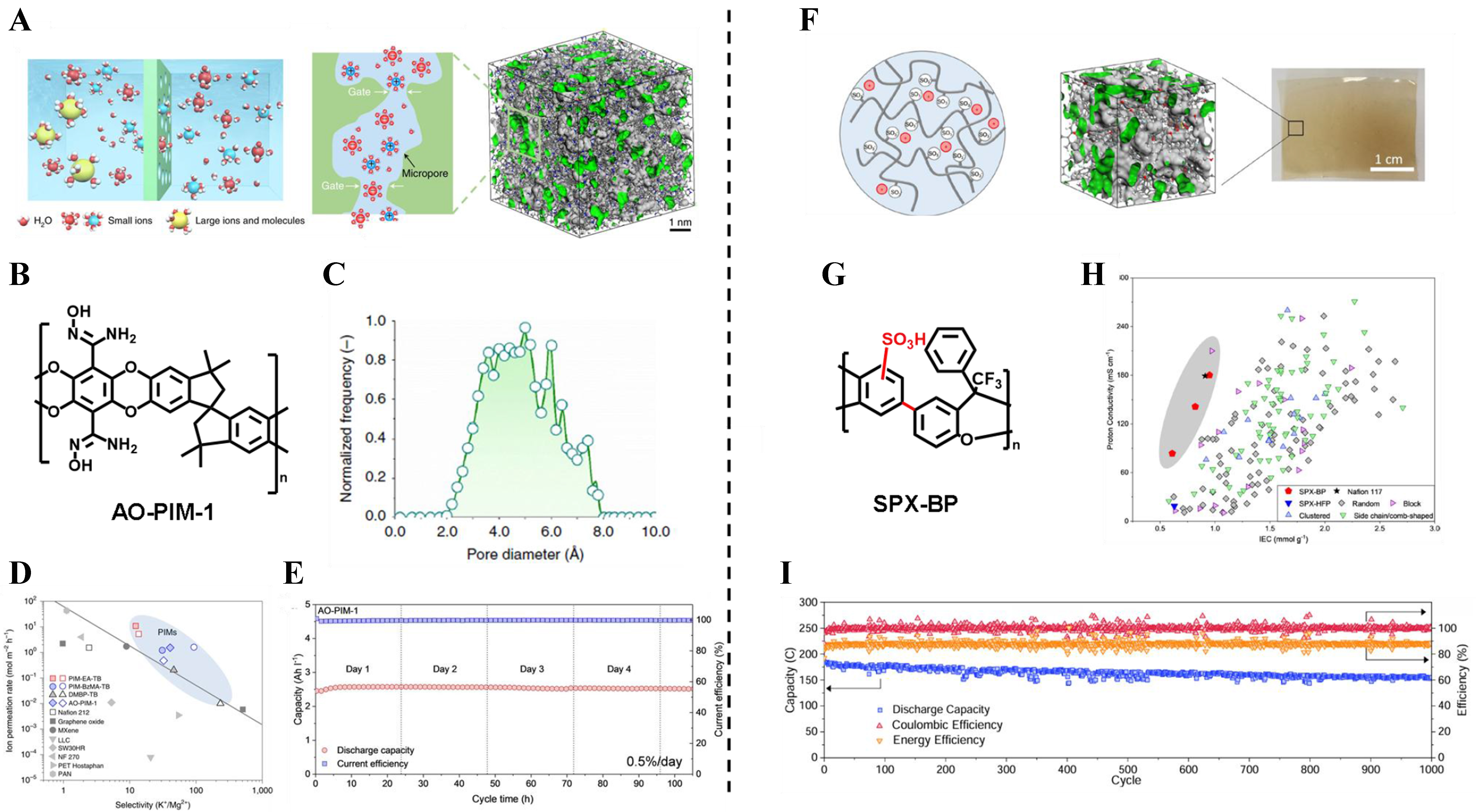
Figure 7. PFPIM membranes in redox flow battery. (A) Schematic diagram of ion exchange in aqueous organic redox flow batteries; (B) Chemical structure of AOPIM-1; (C) Pore size distribution of AOPIM-1; (D) The position of PIMs with other ion-change membranes at the upper bound of K+/Mg2+ separation; (E) long-term stability of the cells assembled with AOPIM-1 membrane at a current density of


